|
Panzer I Ausf A
Part One - Construction
by Brett Green
 |
|
Panzer I Ausf A |

HyperScale is proudly supported by Squadron.com
|
Tristar's Panzer I
Ausf A In the Box |
Tristar is a new Hong Kong based model company. Their first
releases were two very impressive
German
WWII armoured vehicle crew figure sets in July.
Tristar's debut tank is a 1/35 scale Panzer I Ausf. A.
Despite the popularity of WWII German armour modelling subjects,
the early war era has been largely overlooked by mainstream kit manufacturers.
Tristar's subject choice is therefore very welcome. However, the remarkably high
quality of this model is an even greater cause for celebration.
Tristar's 1/35 scale Panzer I Ausf. A is presented on five grey
sprues. More than 100 tiny brown sprues contain the individual track links and
connectors. A final grey sprue includes two very nice figures with alternate
head gear. A small fret of photo etched parts and a decal sheet complete the
package.
The model bears all the hallmarks of a mainstream kit. It
has a one-piece lower hull, narrow sprue attachment points and all of the fine
detail is presented in injection moulded styrene with the exception of the
photo-etched muffler guards.
The plastic parts are very well moulded with no imperfections on visible
surfaces.
Tristar’s styrene has a similar look and feel to Dragon/DML armour kits - the
plastic is slightly soft and easy to work with. Detail on the Tristar kit is better
than a typical Dragon kit though. Tools and tracks are two outstanding areas where this
superiority is quite obvious.
The model seems to have been tooled with accuracy as the primary objective. The
kit does not include overscale connectors or other engineering compromises,
meaning that assembly of some detail parts require forethought and care.
However, the fit of all the main components is very good indeed. I did not need
to use filler on this kit at all.
I built Tristar's Panzer I Ausf A with only a few minor modifications. With its
workable tracks, fine styrene detail and photo-etched muffler guards, this model
will look great straight from the box. However, I did deviate from the
suggested construction sequence.
Tracks
The workable tracks are spectacular but I could see that they would present a
challenge due to the small size of the individual links. I therefore decided to
start construction by completing both track runs. That way, building the rest of
the model would be a breeze!
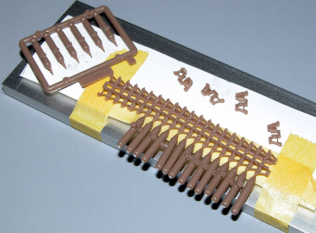
The tracks are moulded in a brown colour similar to Model Kasten
products. However, these track links have been specifically designed for this
model. Each link is supplied as a single piece with the solid guide horn moulded
on. The style of guide horn is absolutely correct for these tracks - they were
not hollow on the full-sized vehicle either. The links are connected to the
sprue at one point, with two more pieces of scrap sprue to remove from each
link. Each tiny sprue contains just two links.
If the links are small, then the track pins are almost microscopic.
Fortunately, the links already have one connector pin moulded on. The method of assembly
is straightforward
-
remove links from sprues
-
slip each link onto the moulded pin of the next
link
-
glue and insert the single separate track pin in the other side
-
wait until dry
-
cut off excess of track pin.
The links can be cut close to the sprue and scrap. I found that no further
cleanup was required when using a new blade.
I put together a simple track assembly jig comprising a flat piece of
aluminium and a length of Tamiya masking tape face-up. I wanted to be able to
bring the length of track close to my eyes when I inserted the track pins (those
holes in the edge of the track links are very small), and the
simple "jig" permitted me to do this.
Removing and assembling the first ten links seemed to take an eternity.
However, I soon got into a rhythm and completed the
job in a period of around 3-4 hours.
The instructions suggest that the track runs should be 87-88 links per side.
Tristar supplies a total of 180 links - 90 per side. However, test fitting
suggested that 88 links would be fairly tight fit with virtually no sag. I
wanted to demonstrate the very slack tracks seen on some operational Panzer Is,
so I added the two spare track links. I was quite happy with the effect.
The lesson here is, take care of every single track link if you want to have
sagging tracks!
I actually ran out of track pins. This was my fault - I destroyed and melted a
few pins during early assembly. Fortunately, fine brass wire can be used as a
substitute to the plastic pins. I just dipped the end of the wire in super glue,
inserted the wire in the hole, waited a few seconds and cut off the wire with a
sharp knife. The links were still workable using this method.
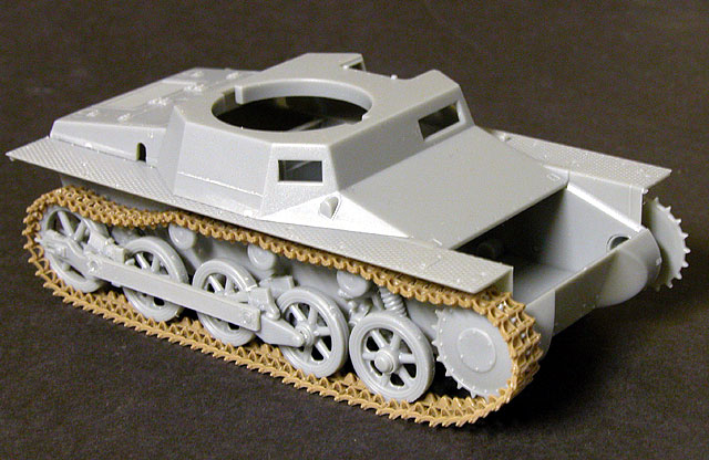
Lower Hull and Running Gear
The wheels and suspension were assembled per the instructions. This area was
very straightforward and assembly was remarkably quick.
Although the road wheels and drive sprockets can rotate, I glued
them in a fixed position. This would simplify painting, and would also give me a
fixed surface to spot-glue sections of the track.

Upon examination of my few photos of Panzer I Auf As in service, it appeared
that the hubs of the return rollers were more prominent than the flat depiction
of centre of the kit rollers.
I beefed up the hubs with discs of plasticard created with a Waldron Punch and
Die set. A styrene “bolt”
was also added to the centre of each new roller hub. This was formed using my
Historex hexagonal punch and die..
While I was at it, I also supplemented the covers/mounts for the external bar linking the bogies
with punched plastic discs.
Before proceeding further, I draped one long track run around the wheels and
drive sprocket. One end of the track was anchored to the bottom of a roadwheel
using superglue and, when I was satisfied with the length and sag, the other end
of the track was glued to the same wheel. Liquid cement was brushed onto the
links around the drive sprocket, and around the idler wheel.
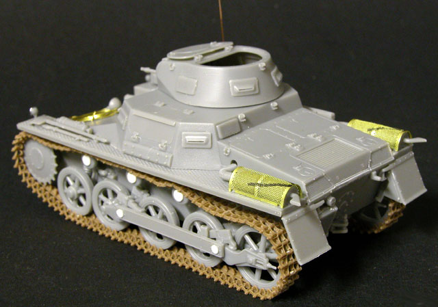
Superstructure
The superstructure is beautifully detailed. The tools and the non-slip pattern on the track
guards are amongst the best that I have ever seen in plastic.
Assembly is logical but I would recommend special attention to the following
points:
-
Part C19 (the panel at the upper hull front) is a
very tight fit width-wise. A swipe with a sanding stick should improve the fit.
By the way, this was the only fit problem I had on the whole kit!
-
Part C13 (the rear upper superstructure panel
incorporating the rear vents) must be glued to the inside of part
A1 (the upper hull) before it is glued to the lower hull. The
instructions do point this out in a diagram, but the arrows are not completely
obvious - at least that is my excuse! I did not realise that C13 had to
be secured from the inside until after the upper and lower hulls were glued and
dried. I did manage to install part C13 from the outside by trimming the excess
plastic and cutting the piece in two, but it would have been easier to avoid the
problem in the first place.
-
The rivets moulded onto the inside of part C25 (the
main hull side hatch) must be sanded off if the hatch is to be displayed in the
closed position.
-
The towing shackle and pin (parts A13, 18 and 19)
is tricky to align perfectly.
-
Care is required when securing the visors, the
skinny sides of the track guards, and the detail to the rear hull plate.
I also made a few changes to reflect an operational machine.
-
Lead foil circles were added as covers for the trackguard mounted lights.
A disc of clear acetate will be used as the lens of the main headlight.
-
I left off the front trackguards because (a) the tracks look
so good and (b) operational photos of Panzer IAs often show them missing.
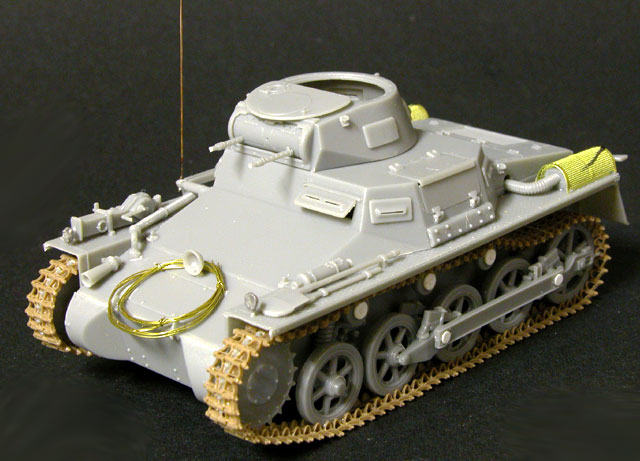
-
A coil of wire was added to the forward superstructure. Once again, operational
photos suggest that this was pretty common stowage.
-
Finally, I added a resin wing nut to the top of the
jack clamp and adapted the aerial to the “up” position. A length of copper wire
was used for the antenna.
Turret
The hatch was left open to permit the later installation of the Commander
figure supplied with the kit.
The only modification to the turret was that the ends of the machine gun
barrels were drilled out.
Continued in Part Two -
Painting, Markings and Weathering
Model, Images and
Article Copyright © 2002 by Brett Green
Page Created 03 September 2002
Last updated 04 June 2007
Back to HyperScale Main Page
Back to Features Page |
 Home
| What's New |
Features |
Gallery |
Reviews |
Reference |
Forum |
Search
Home
| What's New |
Features |
Gallery |
Reviews |
Reference |
Forum |
Search