Eduard's 1/48 scale P-40E Royal Class
Kittyhawk Mk.IA
by Brett Green
|
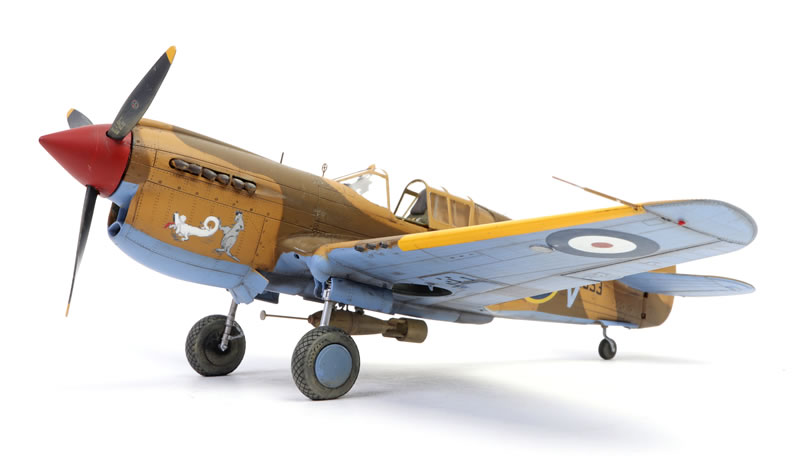
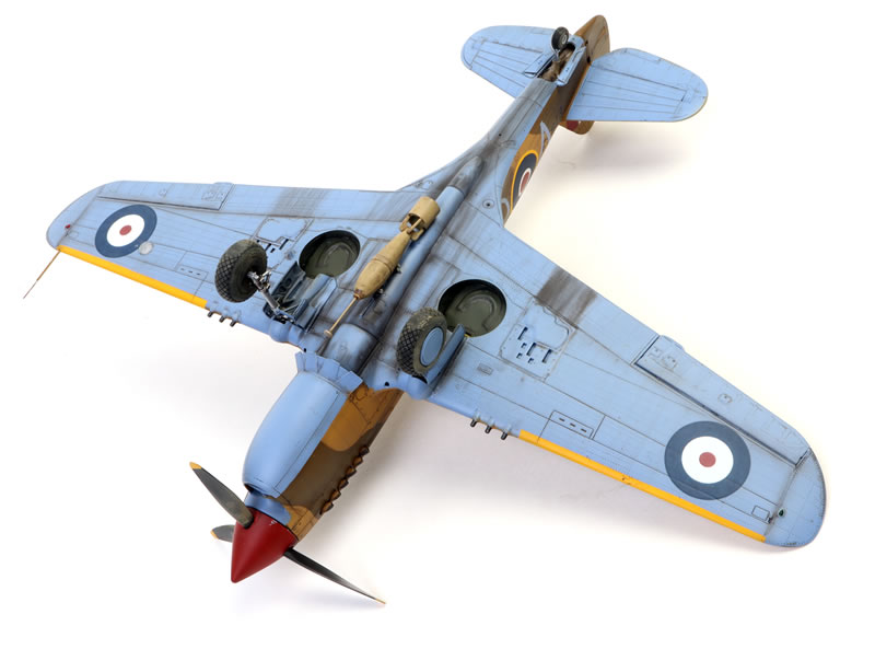
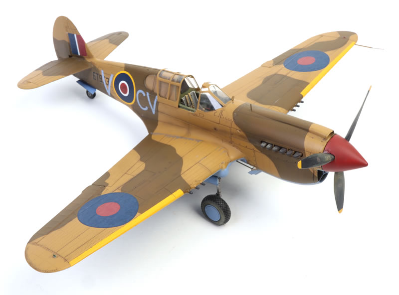
Kittyhawk Mk.IA
S/Ldr. Robert H. M. Gibbes
3 Sqn. RAAF , Egypt, August / September 1942
|

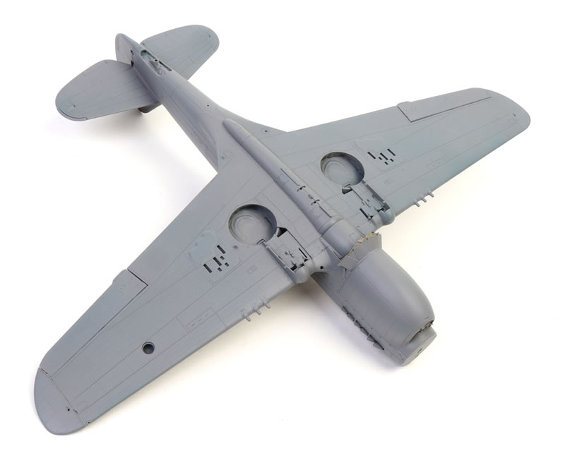
Here is my newly completed 1/48 scale Kittyhawk Mk.IA built from Eduard's excellent P-40E Royal Class Dual Combo package. You can check out my detailed in-box review by following this link.
Spoiler Alert
Building this model was a pleasure. It is the best-fitting Eduard kit that I have built to date. I believe surface textures and general level of detail are their best yet too.
It is also a satisfyingly speedy build.
Don't let this one pass you by!
P-40E Primer
I built my first model from Eduard's P-40E Warhawk Royal Class Dual Combo almost straight from the box, including kit-supplied decals and lots of those lovely Royal Class resin and photo-etched parts.
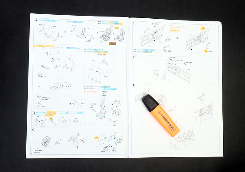
The 26 page instruction book is logical and clearly illustrated but there are lots of alternative parts for the twelve marking options. You need to make sure that you know the appropriate parts for your chosen subject.
I found it very helpful to work through the instructions with a highlighter pen to mark up all the relevant optional parts and colour callouts for my subject.
Most of the instruction steps are straightforward but here are some hopefully handy hints for assembly of the model.
Assembly Hints
Eduard's P-40 Product Manager Richard Plos has kindly provided feedback on my assembly hints. These comments are highlighted in green. Thanks Richard!
I substituted the kit’s plastic parts for a few tricky photo-etched sub-assemblies. These included the open cowl flaps and the tail assembly for the British 250lb bomb. You really don’t lose much detail compared to the photo-etched parts.
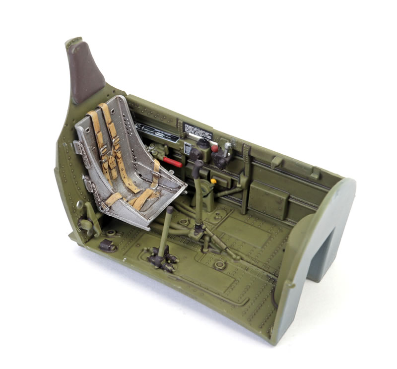
I used the one-piece square-back resin seat option. The shoulder and lap straps are printed in place and look fantastic. I hope that this style of seat will become standard in future.
On page 6, Step I, I could not find Part E51 on the sprue I later did find it on the E sprue between Parts E5 and E6.
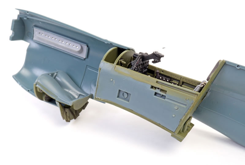
Before you close the fuselage halves, I strongly recommend that you first glue Part F33, the floor of the carburettor intake, to one side of the upper fuselage. The instructions would have you glue this part in place after the fuselage halves are joined but this will very fiddly and fraught with danger.
Eduard says - I would somewhat disagree with gluing the F33 part prior to the fuselage halves assembly. I have built the kit twice and this did not possess any problems. I think gluing it into one halve might be trickier, but cannot rule out it is an option.
If you are using the beautiful 3d resin exhausts, I would recommend fixing the mounts (Parts RP16 and RP17) using a generous amount of two-part epoxy glue. You’ll be applying a fair bit of pressure to the mounts when you are fitting the individual exhaust stacks, running the risk of popping a brittle super glue join.
Eduard says - I agree there is some risk of breakage of the joint. So that is a good point we can modify it in the instructions to emphasize the need for a strong joint between the base of the exhausts and fuselage halve. It would be also possible to install the exhaust pipes prior to the gluing the halves together, but I personally do not favour such a step from modeler’s point of view.
On Page 11, the instructions direct you to fit the undercarriage legs before fixing any of the other undercarriage parts. However, I recommend that the main undercarriage legs should be fitted later in the process. I fitted my legs almost last thing after painting was complete, and then added the various small retraction struts (Parts D42, D43, D44, D45 and D47).
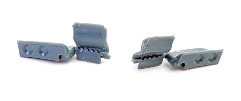
On Page 11, Step M, I was uncertain about how the undercarriage door sub-assemblies (Parts F7 & F42 and F6 & F41) should fit together. I have included a photo here to show you how they should look after assembly.
Eduard says - I personally think the position of the parts in the M step is quite clear, I managed to glue it together successfully when I saw the instructions for the first time and had no clue ... The joining areas are flat and do not allow any other than right position. But maybe we could add the image of the completed subassembly.
On Page 12, I recommend that the leading edge undercarriage caps (Parts F14 and F15) should be fitted before any of the other undercarriage parts. This will considerably simplify alignment and painting.
Eduard says - The recommendation to glue the leading edge undercarriage caps is fine, we've already modified that in the instructions for Limited Edition kit. That’s a good point!
On Page 13, I replaced the plastic pitot tube (Part E26) with a metal industrial light filament.
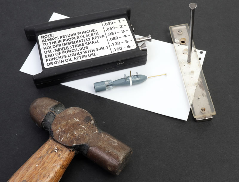
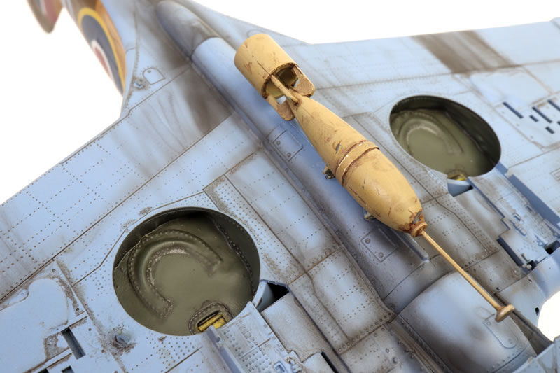
On Page 14, Step S, I used the unmentioned plastic tail parts (Part E46 x 2) for the British 250lb bomb (Parts E9 and E11) instead of the photo-etched parts. I added a strap from a thin length of 0.1mm Tamiya PLA-PAPER, an extended detonator from brass rod and two small disks using scrap plastic and my Waldron Precision Punch and Die. I also drilled and pinned the bomb using brass rod to ensure a strong bond with the bottom of the fuselage.
Also on Page 14, Step S the instructions call out Part E25, 2 pcs as the bomb mounts. However, the mounts are in fact Parts E25 and E26. These parts are subtly different. I used Part E25 (the smaller of the two) at the front and Part E52 at the rear.
Eduard says - There are E25 and E52 parts in the sprue, but it is wrongly stated in the instructions as two times E25. The E52 is to be glued as rear and E25 as front rack. It will be changed in the online instructions and in future releases of the kit.
Paints are mostly SMS Lacquers used straight from the bottle to the airbrush - no thinning required.
I'll be writing this one up in detail Model Airplane International magazine Issue 237 (and quite possibly Issue 238).
Model, Images and Text
Copyright © 2025 by Brett Green
Page Created 18 February, 2025
Last Updated
20 February, 2025
Back to HyperScale Main Page
|
 Home
| What's New | Features | Gallery | Reviews | Reference | Resource Guides | Forum |
Home
| What's New | Features | Gallery | Reviews | Reference | Resource Guides | Forum |