Making Aircraft Navigation Lights
by John Miller

Hobby Boss' 1/72 P-61A Black Widow is available online from Squadron.com
A navigation light, also known as a running or position light, is a source of illumination on a vessel, aircraft, or spacecraft that provides information on a craft's position, heading, and status. Navigation lights are not intended to provide illumination for the craft making passage, only to make other craft aware.
Aircraft navigation lights are placed in a way similar to that of marine vessels, with a red navigation light located on the left wingtip leading edge and a green light on the right wingtip leading edge. A white navigation light is as far aft as possible on the either the tail and/or each wing tip. High-intensity strobe lights are also located on the aircraft to aid in collision avoidance. Anti-collision lights (flashing lights on the top and bottom of the fuselage, wingtips and tail) alert others when something is happening that ground crew and other aircraft need to be aware of, such as running engines or entering active runways.
(Edited from Wikipedia)
Second to the cockpit airframe details such as navigation (nav) and landing lights, are things that viewing eyes are naturally drawn to. Shiny! That’s part of it, of course. Beyond that well executed nav and landing lights add a huge level of detail and are a key part of producing a convincing scale aircraft model.
Unfortunately, kit makers often cut corners on nav lights and rarely provide clear versions, especially in smaller scales (1/72). As a newbie, simply painting nav lights red and green was sufficient but most builders want to up their game as they gain experience.
Replacing solid nav lights with more accurate “glass” versions is not difficult and only requires some patience, a few tools, and learning a few new tricks. What follows are only suggestions based on my skills and experiences. There are as many good techniques for making scale aircraft nav lights as there are modelers making them. With that in I mind, please take whatever you find useful from the following suggestions, combine it with your own experience, and develop a technique that best suites you.
Replacing Navigation Lights |
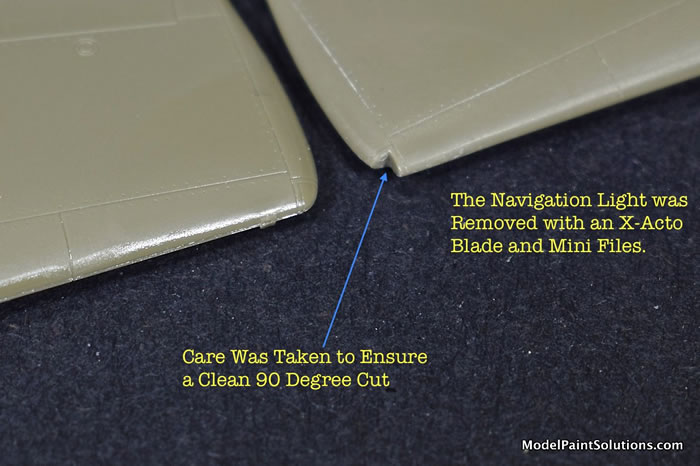
Let’s start with removal of the solid “landing light” from the kits wing tips. This is usually done most easily with a sharp X-Acto blade followed by some clean up with micro files. I tend to stay away from sanding sticks or sand paper at this stage, as I want the removed area to have very clean, sharp edges. Most importantly I try to make sure and maintain a sharp 900 angle at the inboard portion of the light. Keeping the removed area as close to 900 as possible will help align the replacement light for gluing and make for a cleaner installation when done.
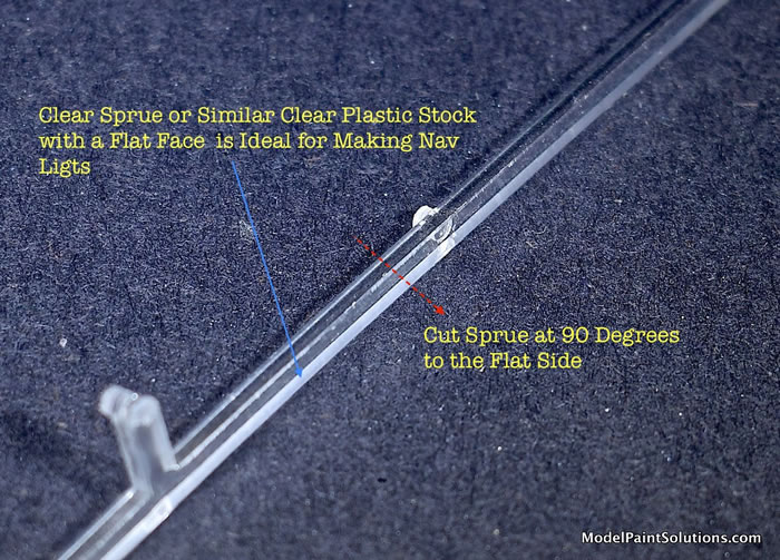
With the solid landing light removed it’s time to cut a replacement from clear plastic. To better fit the 900 angle at the inboard aspect of the nav light, clear plastic with a flat face (often from saved clear sprue) or similar is quite handy as a starting point.
Using a micro saw the clear sprue is cut 900 relative to the flat portion. The end of the sprue is then carefully cleaned up with micro files to maintain a sharp 900 angle.
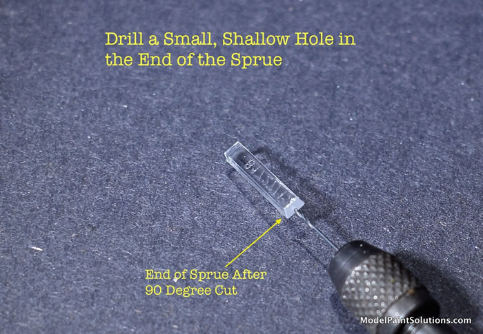
A small, shallow hole is then drilled into the sprue using an appropriately sized drill bit. “Shallow” is the key here as too deep a hole may not leave a sufficient amount of plastic for shaping and contouring the light.
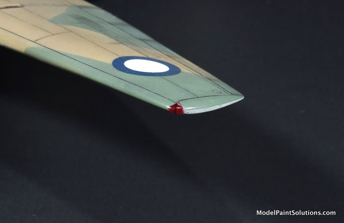
The “bulb” is then replicated by filling the shallow hole with a bit of paint using a sharpened toothpick: red (left or port wing), green (right or starboard wing). Note that some countries use colors other than red and green for these lights so consult your references.
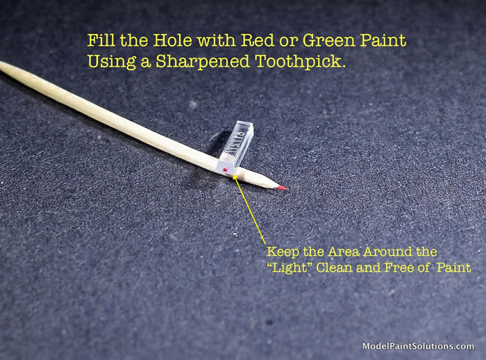
If paint gets onto the clear portion of the plastic around the “bulb” it will compromise the end result. If you get little paint smudge, wait for the paint to dry then gently buff the smudged off with low grit sand paper.
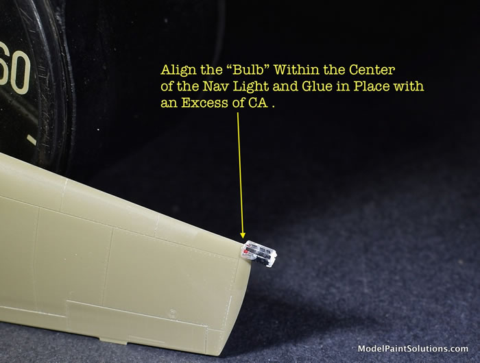
Affix the clear, painted sprue piece into the landing light area using an excess of CA glue. Be sure to align the 900 angle of the sprue with the corresponding angle within the wing tip. A good layer of CA between the clear sprue and the wing as well as around the sprue piece will ensure a bond capable of withstanding the sanding and buffing required for shaping and contouring the light.
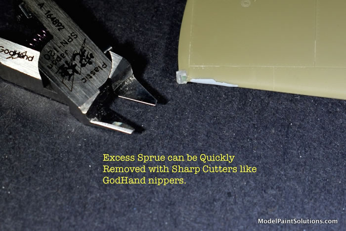
Sharp nippers such as the GodHand brand can be used to remove a lot of the excess clear sprue and save time versus using a file or sand paper.
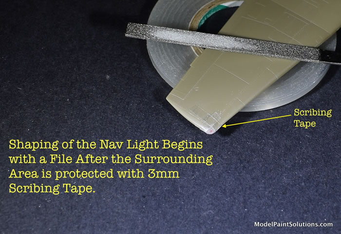
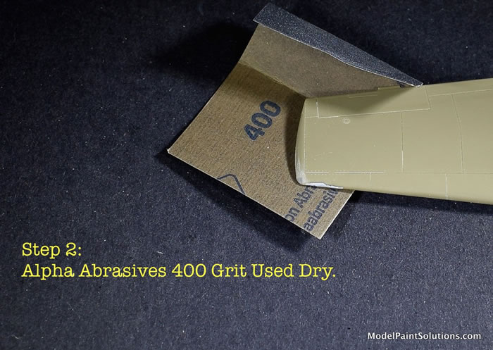
Once the clear plastic has been trimmed Step 1 is usually to perform the initial contouring with a file. Care must be taken to not damage the surrounding plastic so a few strips of 3mm Scribing Tape or similar is placed around the area for protection.
After the initial contouring with a file, I switch to abrasives like sand paper or sanding sticks. In my hands, the more refined sanding papers made by Alpha Abrasives do a good job of removing material while doing less damage to surrounding areas. As I discuss a previous article, “Getting the Scratches Out: Tricks for Clear Parts and Canopies”, it’s best to have a large assortment of abrasives at hand so you can match the grit (more or less coarse) to the hardness of the plastic you’re working with.
For this particular plastic I found that Alpha 400 Grit paper was a good follow-on after filing to begin the process of shaping the clear sprue into a nav light. I often find Alpha 400 handy for many initial sanding/blending jobs. At this point I’m looking to establish the shape of the light and reduce the amount of clear plastic in order to blend it with the wing plastic. With this grit, however, I try to not sand down to the wing plastic: 400 grit is still a bit rough for blending--that’s the next step.
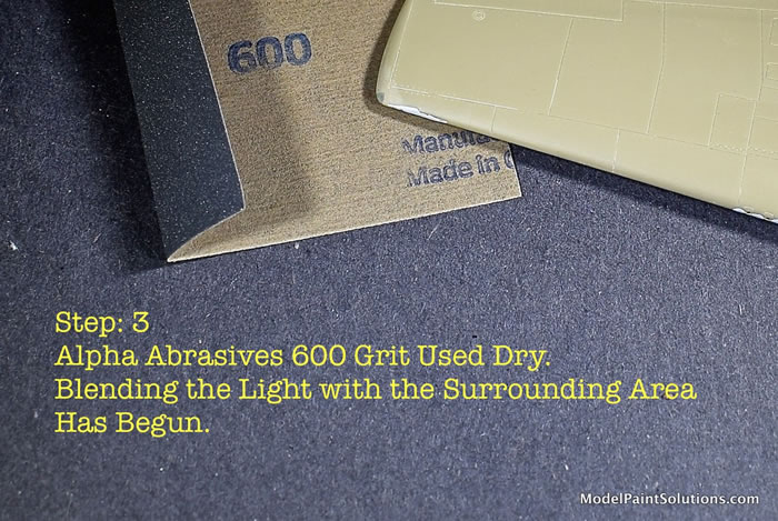
The 400 Grit was followed by Alpha 600, used dry. By this step, most of the light’s shape has been established and my aim is to remove scratches left by the 400 while simultaneously reducing the clear plastic down to the wing plastic; then begin blending the two. It’s best to work slowly with good light and magnification if need be.
Step 3 involved the use of both 1,000 (not pictured) and 2,000 grit Alpha abrasive papers; both used wet. “Wet” here is defined as cool water (volume of a coffee mug) with a few drops (2-3) of dishwashing detergent like Dawn added. While sanding with these abrasives you may notice that the paper really begins biting into the surface only after a bit of fine grit is built up with sanding. The degree of bite can be controlled by regulating how much grit is allowed to build up and how much hand pressure is used. When too much grit accumulates, a quick wipe with a Kimwipe tissue (or similar) and a dunk-wash of the sand paper is required before sanding can continue.
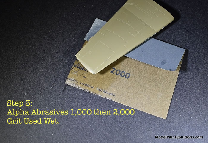
I often have to switch to Micromesh (pad or sheet) of 6- or 8,000 grit for the following step. However, the sprue plastic I used for my Hellcat nav light responded well to Alpha 1,000 and 2,000 sand papers and reached a degree of clarity that permitted me to go straight to Novus-2 Plastic Polish buffed out with a Kimwipe.
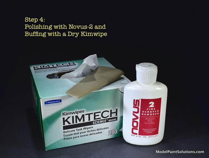
Following a final buffing with a dry Kimwipe, I subjected the nav light to what I refer to as “The Micromesh 12,000 Test”. Micromesh 12K is a mild abrasive; so much so, that in my hands, really clear plastic is little affected by buffing with Micromesh 12K. To assess this, I buff a small area of the clear part being tested and compare the area with areas not buffed. If there is an appreciable increase in clarity after a buffing with 12K, chances are the part could benefit by a buffing with 6- or 8,000 Micromesh before returning to the 12K for a final buffing. If, on the other hand, a buffing with 12K doesn’t result in a large increase in clarity, the part is probably about as clear as you’re going to get it: job done.
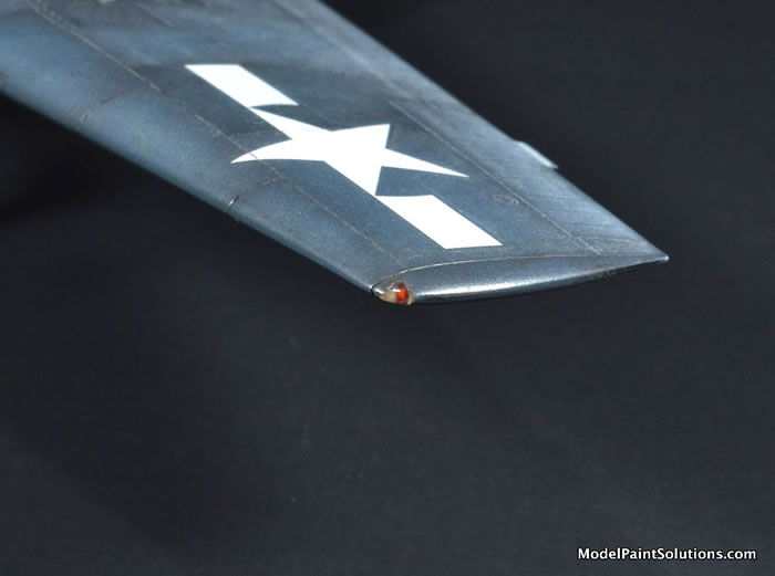
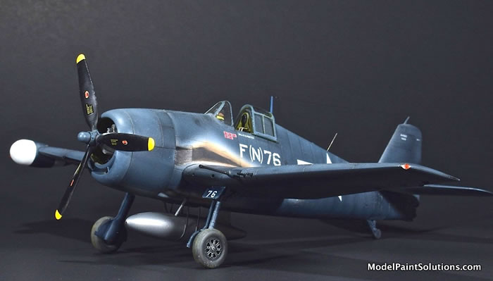
With both the port and starboard nav lights complete, the wings were added to my Eduard Hellcat and the project took a big step closer to the paint booth: my favorite part ? But, that’s for another article…
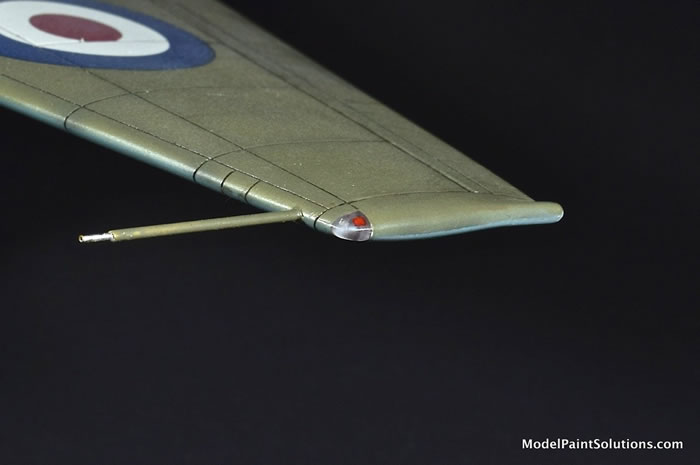
In addition to replicating nav lights with clear covers and colored bulbs, the same technique can be used to make colored nav lights. The main difference is the use of a colored piece of donor plastic and sources for such abound. As an example, I give you colored plastic beads that can be found in many craft stores, often in the decorations or jewelry-making sections.
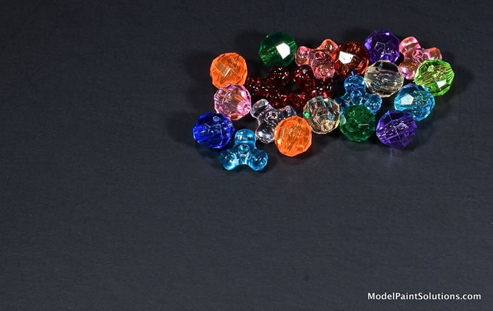
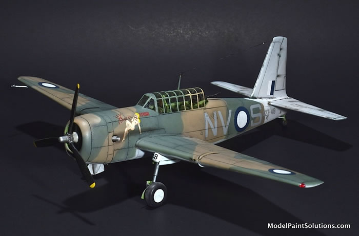
These beads were the source for the nav lights on my old Special Hobby 1/72 Vultee Vengeance. Both the port and starboard nav lights were made from colored plastic beads that were first put in a vice and cut with a small saw producing pieces with clean 900 angles. These were then affixed with CA thence shaped and blended in-place using the same techniques as described above for the Hellcat lights.
Thanks for reading along. I hope you found something useful.
Replacing the solid nav lights on an aircraft kit with clear versions is an investment of time but the result adds a level of realism that goes a long way to making a build more convincing.
I suspect the most challenging aspect of this technique is learning to file and sand the clear plastic into an appropriately shaped nav light; at least it was for me. Here practice, repetition, and patience are key. Remember, if too much plastic is accidentally removed by a careless swipe of a file, it’s simply a matter of removing the damaged light by X-Acto and micro files and starting again: been there, done that.
Now I gotta go paint something!
--John
For more on this article visit Modelpaintsolutions.com
Text and Images Copyright © 2020 by Model Paint Solutions
Page Created 13 May, 2020
Last updated
13 May, 2020
Back to HyperScale Main Page
Back to Reviews Page

|
 Home
| What's New |
Features |
Gallery |
Reviews |
Reference |
Forum |
Search
Home
| What's New |
Features |
Gallery |
Reviews |
Reference |
Forum |
Search