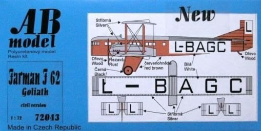
AB Model 1/72 scale
Farman F.62 Goliath
Civil Version
by Tim Nelson

Hobby Boss' 1/72 P-61A Black Widow is available online from Squadron.com
Civil aircraft of the inter-World War years are among the most fascinating, colorful, and appealing genres of aviation. This era shaped the modern transportation world, with profound influence on technology, history, and culture. Yet, modelers have long been underserved by kits of these important subjects in favor of endless variations of ever-popular World War II subjects. That state of affairs has changed slightly in recent years, with a smattering of kits emerging to delight the “golden age” civil aircraft modeler. Among these is the AB Models Farman Goliath.
History
Initially designed as a bomber, the Farman Goliath instead became one of the most significant civil aircraft of the immediate post-World War I era. The type set several altitude and distance records in 1919, positioning the Goliath as a high performer worthy of public confidence. Goliaths played a major role in establishing the practicality, safety, and economic viability of the emerging European airline industry in the 1920s.
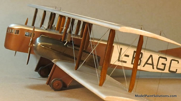
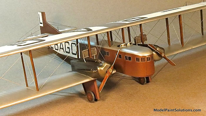
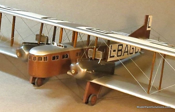
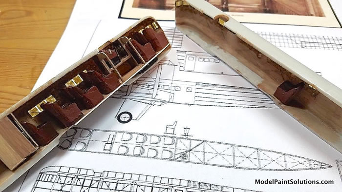
Goliath structure was primarily wood, with wings, empennage, and rear fuselage skinned in fabric. Plywood girded the forward fuselage. Copious windows were provided to the twelve passengers, especially to the four seats in the prominent “prow” up front. Diagonal cable bracing is apparent along the passenger cabin walls. Photos show variations in cockpit installation, but the majority of airframes appear to have accommodations for a single pilot on the port side, with the starboard side open to the passenger cabin – must have been chilly! The Goliath also featured one of the first fully functional airborne lavatories.
Approximately 60 Goliaths were built by the Farman works in France. Early airframes were powered by Salmson Z.9 or later CM.9 water-cooled radial engines. Several other engine types were eventually fitted in production or via retrofit.
Eight Goliaths were built under license in 1927-28 by the Czech firms Avia and Letov. These aircraft were modelled on the F.62 but exhibited some refinements relative to earlier models, in particular the streamlined nacelles for its Skoda-built Lorraine-Dietrich inline engines.
A Goliath fuselage survives in the Musée de l'Air et de l'Espace at Le Bourget Field in Paris.
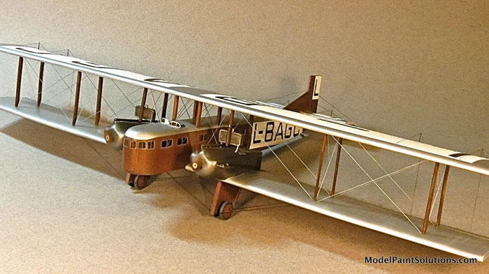
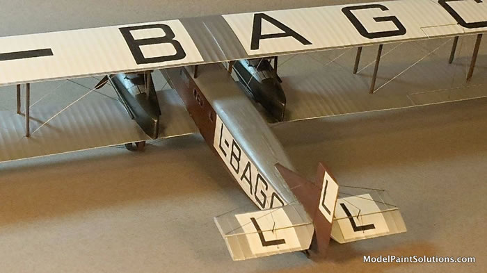
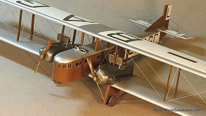
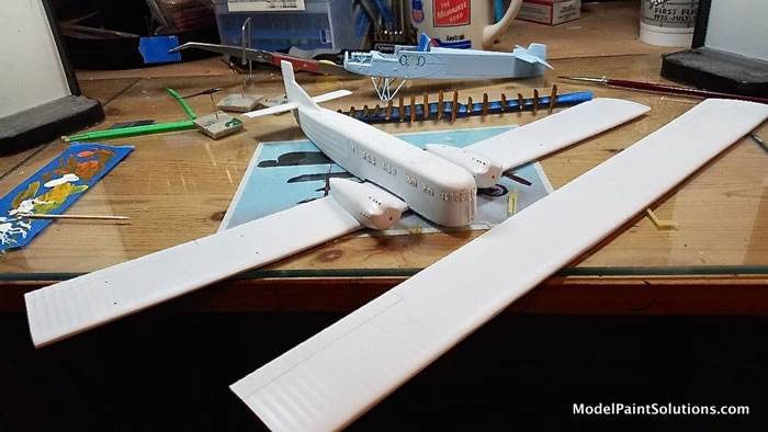
The AB Model kit is all resin, with generally decent surface detail. The model represents Goliath L-BAGC operated by ?eskoslovenské státní aerolinie (?SA). The wings in particular are a highlight of the kit. About 14 inches in span, they are thin with appropriate rib detail, and very crisp at the trailing edges; a tour de force of resin casting. Each left/right half of the upper and lower wings must be joined together to form the full span wing. I installed dual music wire rods to provide strength, then carefully mated the wing halves with 5-minute epoxy.
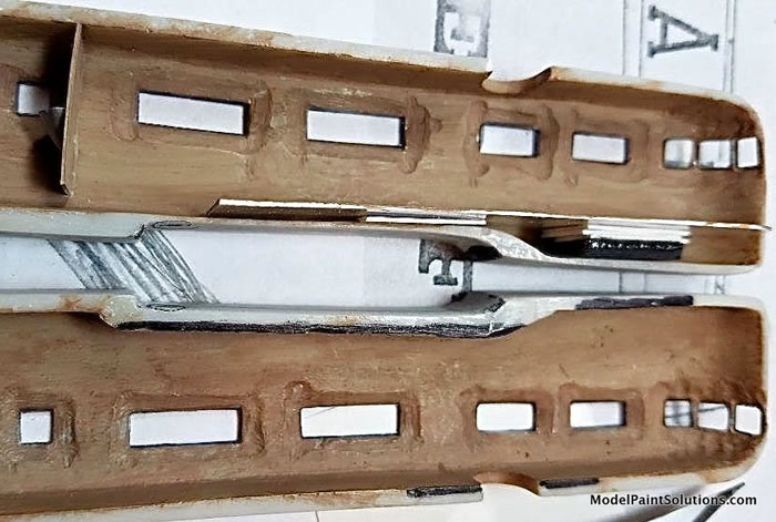
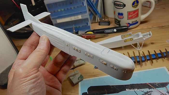
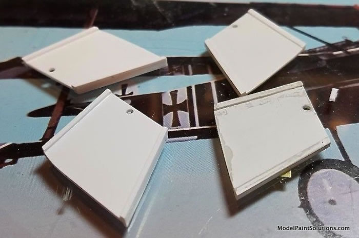
The fuselage exterior captures salient features of the Goliath, including the fabric texture of the aft section. There were some molding irregularities in the “fabric” that were a challenge to correct. The fuselage walls are exceedingly thick, which makes for difficulties in installing interior cabin features. The engine nacelles are solid resin, and I mated them to the lower wing early in the build to smooth seams and build up a lower front fairing from putty.
No decals are provided; instead, Oramask 810 masks are included for the various civil markings. The masks in my kit, purchased several years ago at the Aviation Megastore / Luchtvaart Hobby Shop in Amsterdam, did not age well and could not be used. More on that below…
A fret of photoetch is provided for the control horns, but the horn shapes do not match the long and narrow shapes evident in photos. More on that as well…
The basic elements are there, but some scratchbuilding and modification skills are necessary for a more satisfactory result:
- A basic cockpit enclosure is provided, but in order to match the port side installation seen in photos and drawings, I cut it down the middle. Other cockpit details were scratchbuilt using the Brengun 1/72 “WWI details” photo-etch set, some spares box bezels, and punched discs.
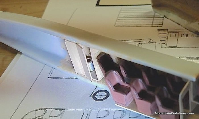
- The cabin is darkly visible through the many windows, and directly down through the pilot’s cockpit opening, so some added details are worthwhile. All passenger seats are provided, which appear on the heavy side relative to the wicker style seats seen in most photos, but I used them nevertheless. Items such as bulkheads and a floor must be fabricated. The diagonal cable bracing is quite noticeable in photos, so I deemed it necessary to emulate with some silvery beading wire stretched across appropriate windows. A little bulkhead “art” helps set the mood. The lavatory is a must, so a styrene enclosure was prepared with a “loo” and wash basin fabricated from spares box bomb tail cone and half-nose; swords to ploughshares!
- Much filling and drilling was required to correct interwing strut locations. Careful preparation and fit-checking early on will save much grief here later. Of late, I have been making strut dimples with about a #50 drill bit, then sanding the ends of the struts into a rough cone shape to seat inside. It is a relatively painless and quick way to proceed, with no tedious drilling or wire insertions required. Rigging will provide the required strength, just as on the prototype.
- All rigging holes were carefully spotted and drilled in advance. Over 150 holes were required.
- Exhaust plumbing was scratchbuilt from metal wire, styrene rod, and brass tubing. The kit parts were too vague, and suffered breakage anyway.
- Lower wing outrigger struts were fabricated from styrene.
- Cabin window openings were cleared out and filled with CD “jewel case” material. I used Aizu 0.4mm tape to define panes, masked the clear areas with small Tamiya tape squares, then removed the Aizu. I later redid the nose section and used painted Aizu tape to actually represent the panes there. All of this ended up not quite as crisp as I’d like, but a large number of hours would be required to really do these many windows justice; I’m relying on the distraction of other things to look at to keep you from noticing. Cockpit windscreens were prepared from clear “viewfoil” material and installed at the very end.
- Kit landing gear struts had numerous molding mars, and I opted to just replace them with new assemblies fashioned from sheet and strip styrene.
- Kit propellers were a bit thin but I used them, reshaping the tips to match photos of the Czech airplanes. They were given the typical artist oil wood treatment, sealed with Pledge Floor Gloss (PFG, a.k.a. “Future”), then I used a silver Sharpie to deftly create leading edge metal cladding. Prop bosses came from the very handy Brengun “WWI Details” photo-etch set.
The very thick fuselage halves required major thinning around the window locations. Fortunately, the interior cabin walls really cannot be seen after assembly. Basic fit of the fuselage halves was decent, after further thinning of the floor section to allow for my cabin to remain horizontal once installed.
Some seam-filling was definitely required, and proved quite difficult on the aft fuselage section with the fabric texture. I did my best to blend the seam with the raised longeron lines. Some imperfections of surface texture were cleaned up to some extent with putty, but I reached a point where I was reasonably content with an overall distressed look (the model, not the modeler).
The major challenge of basic assembly is the join of lower wing to fuselage. The basic kit is molded with a concave recess to receive the lower wing; however, photos clearly show the lower wing passing through the fuselage, flush with the lower fuselage surface. This required major grinding of the lower fuselage, and also the mid-section of that already very thin lower wing. Much sanding, checking, and dry-fitting was done here to reach an acceptable flush fit of the lower wing to the fuselage.
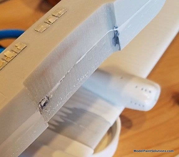
The critical wing/body join was accomplished with 5-minute epoxy. Gaps were filled with Perfect Plastic Putty. A strip of sheet styrene was cut to shape as a later cover of this area on the bottom.
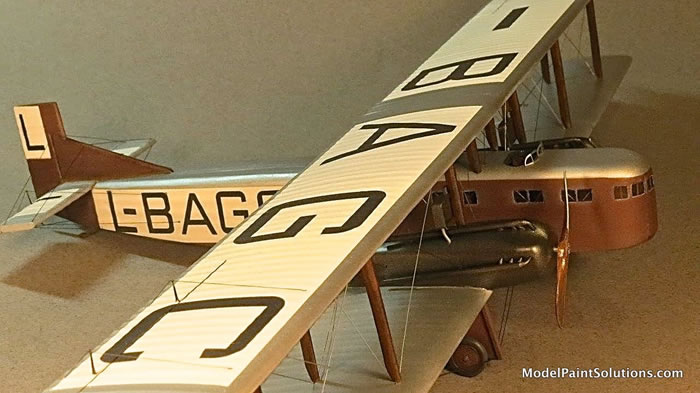
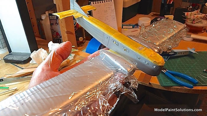
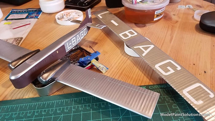
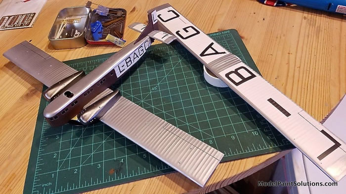
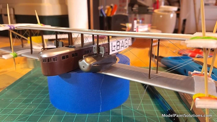
I always look forward to the painting stage but this project presented some challenges, especially with respect to those large and thin wings. I decided on a 2-step process to prime them, one side at a time. Knowing that large white blocks would be a background for the civil registration letters, I opted to hit the wings with Krylon ColorMaster rattle-can primer in white satin. It goes on alarmingly heavy but has great coverage and dries quickly to a rock-hard finish. The fuselage was primed with Alclad gray primer using my 20 year old Paasche H airbrush.
The sequence of painting is always an important strategy to work out in advance. In this case, much of the model would be silver, to emulate silver doped linen and painted wood. I decided this would be an appropriate subject for use of my dwindling supply of Floquil Old Silver (which I still consider to be the finest all-purpose silver paint ever bottled.) Silver also serves as a nice secondary primer to highlight significant flaws missed earlier.
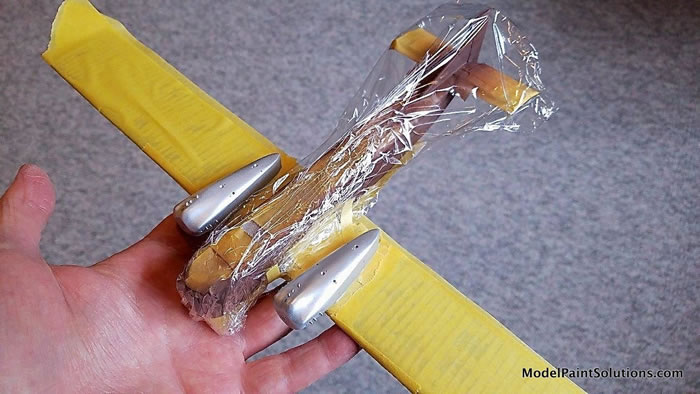
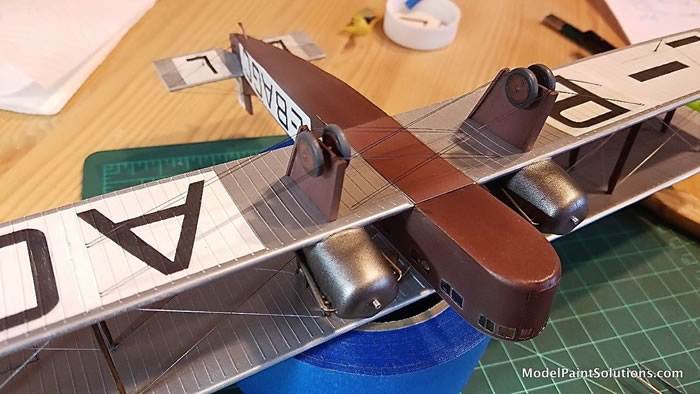
After masking to protect the silver, I then applied a bit of subtle fuselage preshading with Mission Models MMP-072 Medium Grey. I then sprayed the civil registration blocks on the aft fuselage and tail with Mission Models MMP-001 White. Further masking was applied to preserve the white areas, then the fuselage was treated to Mission Models MMP-012 Rotbraun. Then, the engine nacelles were isolated for a metallic finish; first with a coat of Tamiya X-1 Black thinned with Vallejo Thinner and a bit of Tamiya retarder, then (when fully cured) Alclad Duraluminum.
As noted above, masks were provided in lieu of decals. Unfortunately, the Oramask 810 stencils, like George Constanza, experienced dreaded shrinkage during several years of shelf storage. They were not usable, so I took the plunge into an uncharted new world of homemade masks. I had been considering acquiring an electronic cutting tool for some time, pondering offerings from Cricut and Silhouette. I opted for the Silhouette Cameo 3 and ordered one from Micro-Mark. The included software allows importing images, which can then be manipulated or traced to define the cut lines the tool will perform. There are many online resources and social media groups devoted to these tools, and they provide a liberating capability for custom markings of all sorts, limited only by the modeler’s imagination.
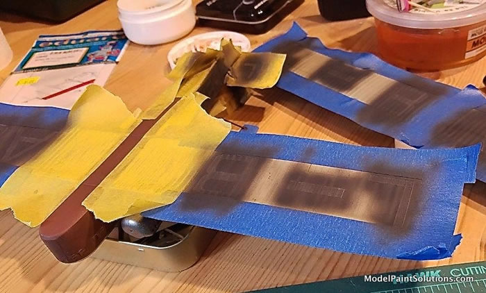
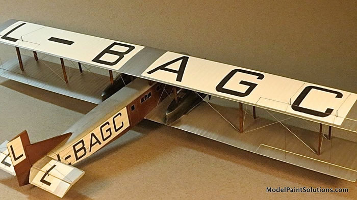
I scanned the kit sheet, and generated the new vector art cut lines using the Silhouette software. The Oramask 810 material is a thin vinyl-like material, with a low tack surface. After some online consultation and a little experimentation, I found the material easy to use. It would not be ideal for significant compound curves, but worked well for the slab surfaces of the Goliath. After applying rectangular masks over the areas to remain white and accomplishing painting of the surrounding areas, I then applied masks for the registration letters. It is wise to lightly burnish the edges where paint will be applied. The civil registration letters were laid down with repeated light coats of a 50/50 mix of Mission Models MMP-047 Black and MMP-001 White. A minor amount of touchup was needed in a couple of spots where a bit of bleed-through occurred.
I installed the scratchbuilt engine exhausts and the kit radiators at this point, knowing these areas would be really hard to access later. The entire model was then painted with Testors Metallizer Sealer, which lends a very nice scale eggshell finish.
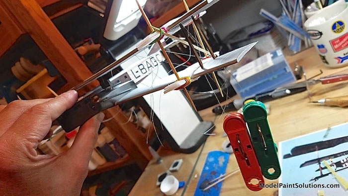
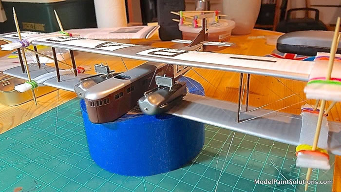
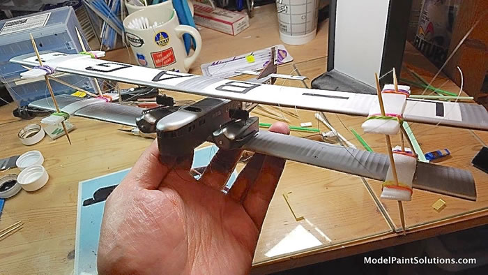
After all this work, the time finally arrived to mount the top wing and begin rigging. The installation of the top wing is greatly aided by the clever homemade jig designed by Seattle-area modeler Jack Matthews. I call this jig the “Godsend” tool, and it can be fabricated for material costs measured in pennies and a few minutes of labor. The tool allows for careful positioning of the top wing in three dimensions, and keeping it there while struts and rigging are installed. I’m not really sure how I would have accomplished these steps on the Goliath without this ingenious device.
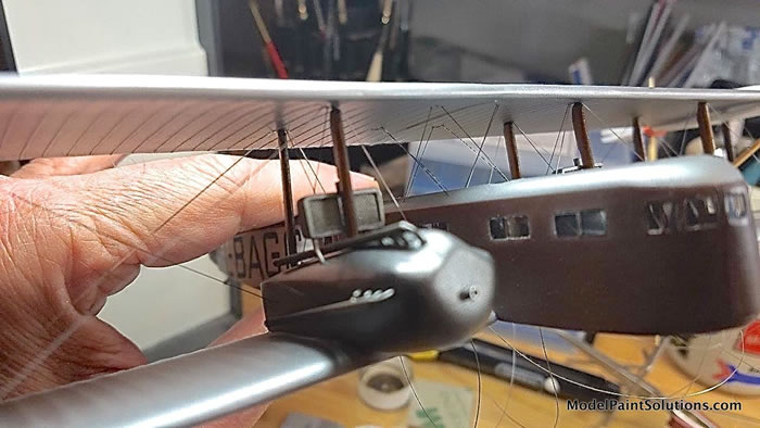
For the Goliath, after studying photos and diagrams, and assessing the model, I opted for an approach a little different from the typical inside-out rigging sequence. The outer wing allows for simple pass-through holes through the bottom wing, and here I chose to use Trilene 4-lb fishing line treated with a Silver Sharpie. The strength of these runs is critical for overall structural integrity of the model. The lines can be initially anchored in the top wing prior to installation. After mounting the top wing, the lines were threaded through the lower wing holes, tensioned and secured from the bottom, then cut and faired. For the inboard rigging, which terminates in the engine nacelle or in the cabane strut area in the top fuselage, I opted for the ceramic Wonder Wire terminated in double-blind holes. All control cable runs were executed with Uschi “Rig That Thing” line, which can be secured on each end with a bit of slack, then tightened up with heat. In general, all struts and rigging were secured with Bob Smith thin CA glue, applied with the delightful Looper 2.0 tool.
Regarding control horns, the kit comes with a photo-etch fret for this purpose. However, the crescent shapes do not look much like the narrow and slightly arced horns seen in photos. I scrounged Skyway Model Shop in south Seattle for a suitable substitute and found the Eduard set of Spitfire Mk. XVI landing flaps, which has many spiky appendages that look the part. I separated and repurposed these shapes and they appear more faithful to the prototype.
Installation of the landing gear assemblies was a real challenge. The struts are really too thin to accept internal rods for a nice, positive attachment to the lower wing. Thus, I was left to rely on a butt joint for these critical load-bearing structures.
Actual Goliaths show extensive cross-bracing on the landing gear and it is absolutely functional and essential to absorb shear loads; I used Wonder Wire for this purpose. Because of the flexibility of the large and thin resin wings, it was nearly impossible to get the model under its normal resting load and properly access the wire terminals to secure them. It was an iterative process and these runs, eight sets of parallel wires, are not as straight and true as I’d like.
During the custom mask creation process discussed above, I also designed my own mask for the small dual pilot windscreens seen on the Czech Goliaths. These were applied to “viewfoil” material, the outer border carefully cut, then simply swiped with a silver Sharpie. Installation of these windscreens, the lower fuselage wing/body join cover strip, and the lower wing outrigger struts, completed the build. A final hair dryer treatment helped take up slack on the Trilene line from all that handling.
There are a couple of things I botched. One is the angle of the exhaust lines running aft along the sides of the engine nacelles. I didn’t notice early enough that the originating location holes on the kit were a bit too high, so to avoid rigging line interference, I had to angle the exhausts downward; they are actually parallel to the wing surface. I also misjudged the geometry of the radiators installed immediately aft of the forward struts on the nacelle. My placement of the nacelle holes for the radiators didn’t allow enough strut clearance, so I had to bend the radiator “piping” aft as well as sand the aft edge of these struts to permit everything to occupy this space. Oh well, next time…
I’d like to thank AB Models for finally creating a kit of this very important and long neglected subject. It was a challenging build and definitely not for beginners. This is the largest aircraft model I’ve built since the Monogram B-52D I slapped together in 1973, and without question the most flexible model I’ve attempted. You’ve read about the difficulties, but in the end, it was a satisfying project and it all blends together in goodness.
This model and others of the early civil air transport era will be on display at The Museum of Flight in Seattle from December 6, 2019 to March 5, 2020.
European Transport Aircraft, John Stroud, Putnam & Co., Ltd, 1966
“Wings of Peace: Farman Goliath”, John Stroud, Aeroplane Monthly, December 1983
Resources
AB Model
For more on this review visit ModelPaintSolutions.com
Text and Images Copyright © 2019 by Tim Nelson
Page Created 6 June, 2019
Last updated
6 June, 2019
Back to HyperScale Main Page
Back to Reviews Page

|
 Home
| What's New |
Features |
Gallery |
Reviews |
Reference |
Forum |
Search
Home
| What's New |
Features |
Gallery |
Reviews |
Reference |
Forum |
Search