Building Tamiya's 1/48 scale
F-14A Tomcat Test Shot
Part Two - Construction Continues
|
|
Grumman F-14A Tomcat |

Tamiya's 1/48 scale F-14A Tomcat will be available online from Squadron
Last week I started building the test shot of Tamiya’s forthcoming 1/48 scale F-14A Tomcat, as reviewed earlier on HyperScale.
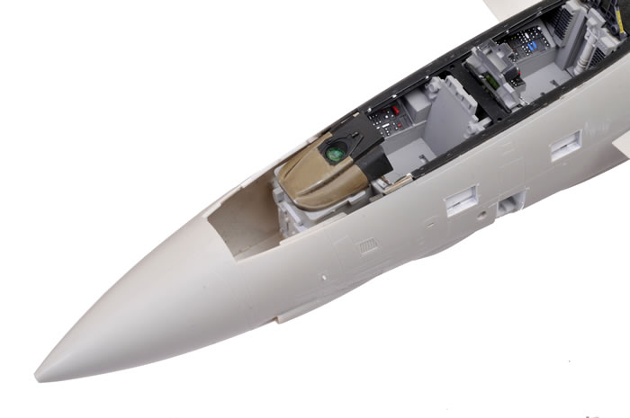
In the first instalment, I built the cockpit and the nose section.
This time, I will be covering the balance of construction.
Building the model has been a joy. Engineering is clever and fit is superb.
In general, I followed the instructions but there were a few exceptions and notes that I will summarise up-front:
-
Nose weight is not mentioned in the instructions. It is not required. I tested the almost-complete model with undercarriage legs and wheels clicked into place. The nose wheel remained securely on the ground with the wings swept forward and also with the wings swept back.
-
In Step 13, I added a spot of super glue to each polythene cap inside Parts B8 and B9. This stops the poly caps from moving inside the housings, and allows the horizontal stabilisers to hold any pose but still remain moveable.
-
In Step 14, there is a small step at the V-shaped join between the upper forward and rear fuselage sections. This is supposed to be there, so don't try to fill it!
-
You don't have to glue the wings in place in Step 21. I left the wings off, which makes painting much easier. If you choose to glue the wings in place, you can do this at the very end.
-
Instructions would have you fit the undercarriage legs and doors in Steps 27 and 28. I recommend that these should only be fitted until after the model is otherwise complete. The fit of the gear legs is excellent, so you'll have no troube fitting the painted and weathering undercarriage at the end.
-
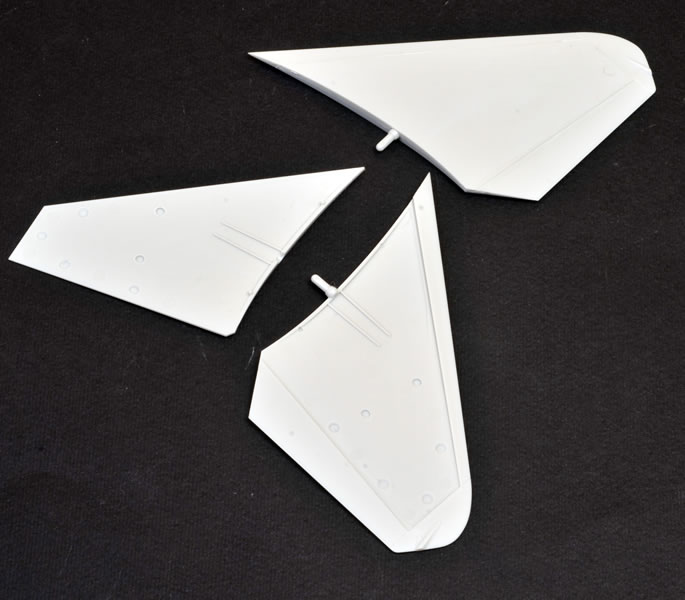
Similar to the wings, you don't need to fit the horizontal stabilisers in Step 29. Paint them separately and add them when the model is finished.
-
In Step 35, delay fitting the missiles until the model is completed and painted.
-
Also, I received the full production package of the kit today, and it is worth noting that the dot-screen effect seen on some of the smaller decals is not present on the final decal sheet.
Now let's take a look at the balance of construction step by step.
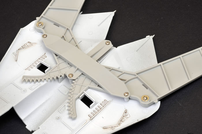
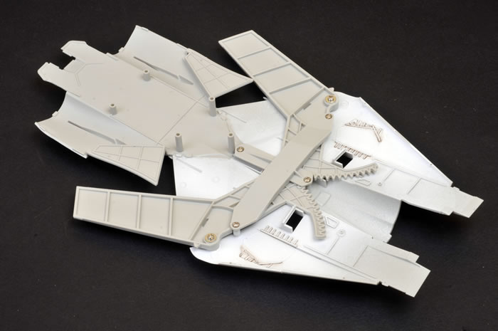
The swing wing mechanism is held in place with screws and washers.
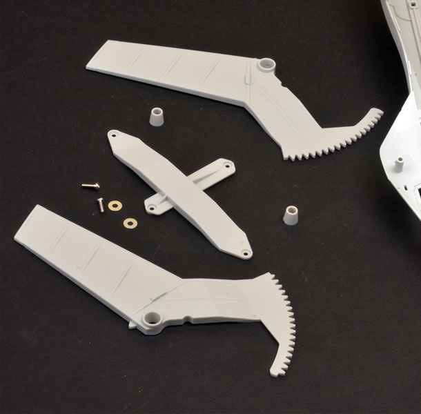
These are screwed in tight.
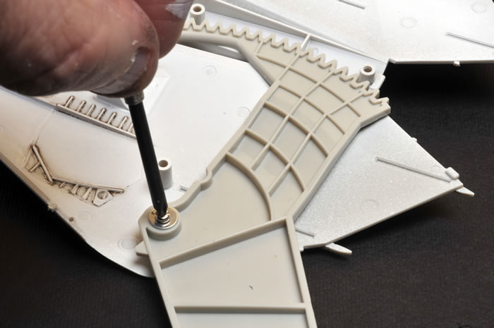
The second geared wing mount is also screwed in place. If the gears are not properly meshed at this stage don't worry - you can still adjust them any time before the lower fuselage is glued in place.
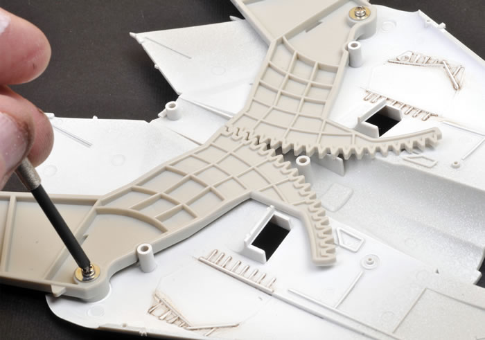
The swing wing mechanism is held in place with a cruciform saddle, also held in place with screws. Note that I painted and weathered the areas that would be seen through the open wheel wells before adding the swing wing mechanism.
The intake ramps are designed to be posed open. They are made up from three parts each.
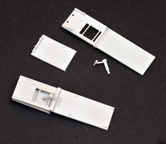
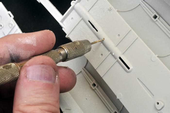
Don't forget to drill out the holes for your choice of weapons. The instructions offer three different configurations.
The lower rear fuselage section as viewed from below. I painted the main wheel bay white before proceeding further.
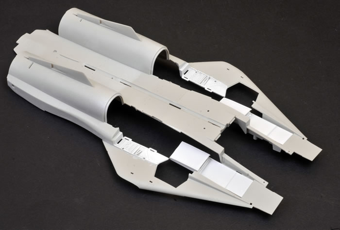
The sidewalls for the main wheel bays are made up from four separate parts. These were all painted and weathered while they were still on the sprues.
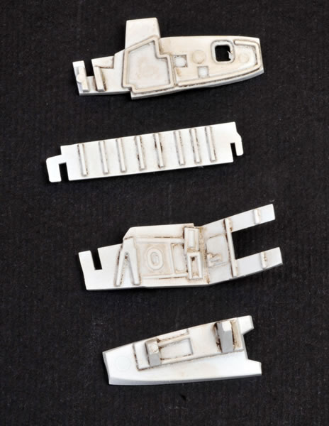
The four sections interlock perfectly.
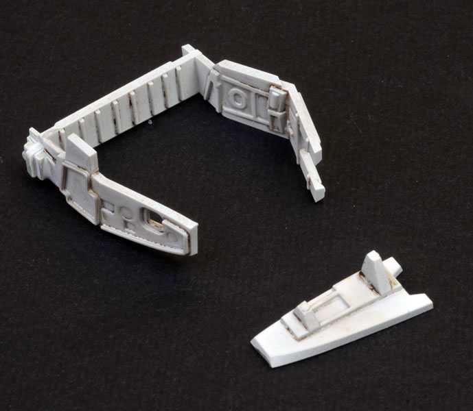
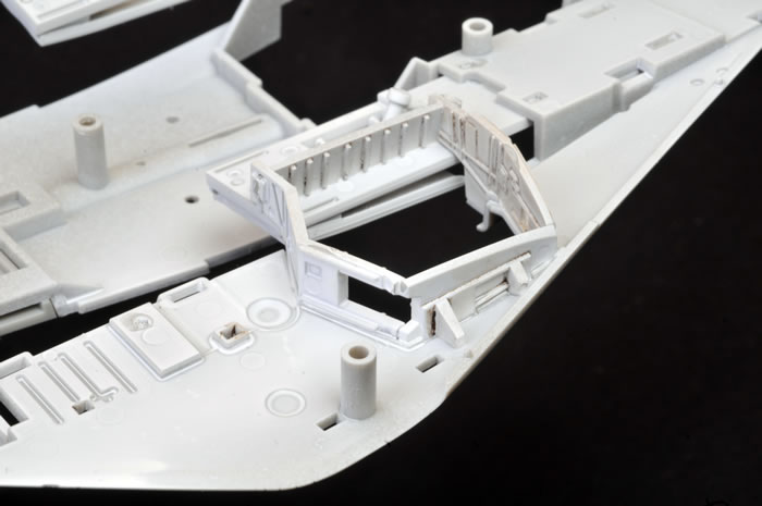
The completed sidewall assemblies are glued to the inside of the lower fuselage
The horizontal stabilisers are poseable thanks to the use of polythene caps. Following test-fitting, I thought that the fit was a bit loose as the poly cap moved freely inside its housing. I applied a spot of super glue to the outside of both polythene caps, which effectively locked them in place. This delivered a firm press fit for the horizontal stabilisers, but still allowed them to move.
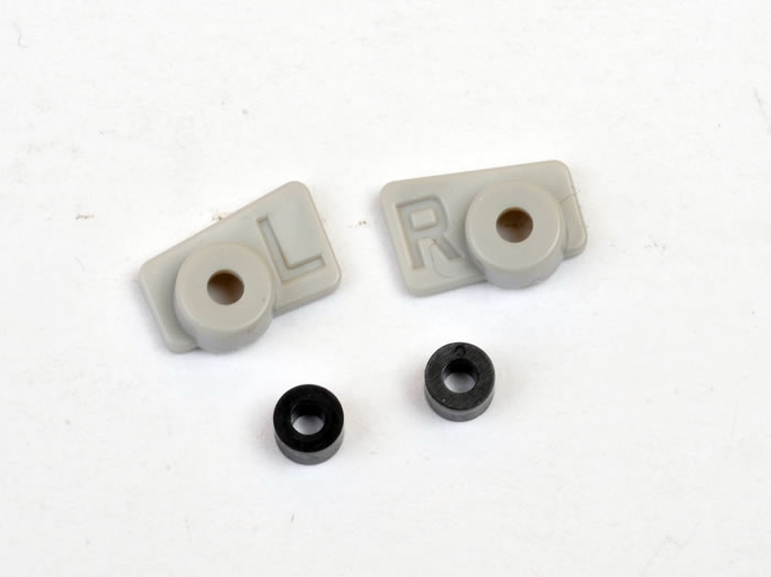
The poly cap and its housing glued in place.
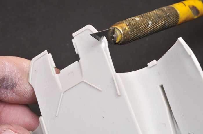
A small wedge of plastic has to be sliced from the upper fuselage on either side of the burner cans. A sign of things to come perhaps?
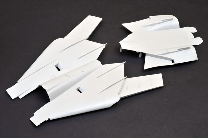
The upper forward and rear main fuselage sections ready to be brought together.
The two upper fuselage sub-assemblies are joined using interleaving locating tabs. There is a slight step at this join but don't worry - it is supposed to be there!
A view of the inside of the upper fuselage, including the completed swing wing mechanism.
The upper and lower halves have been joined here.
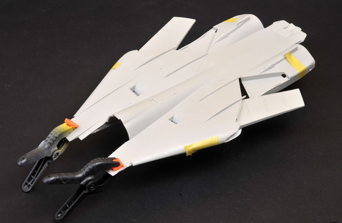
A view of the assembled main fuselage section from below. I used tape and clamps to hold the main pieces in place as the glue set.

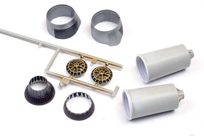
Once again, most of the exhaust and intake parts were painted and weathered while they were still on the sprues.
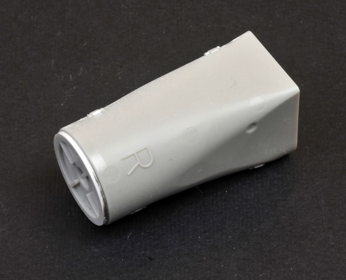
Intake and fan parts.
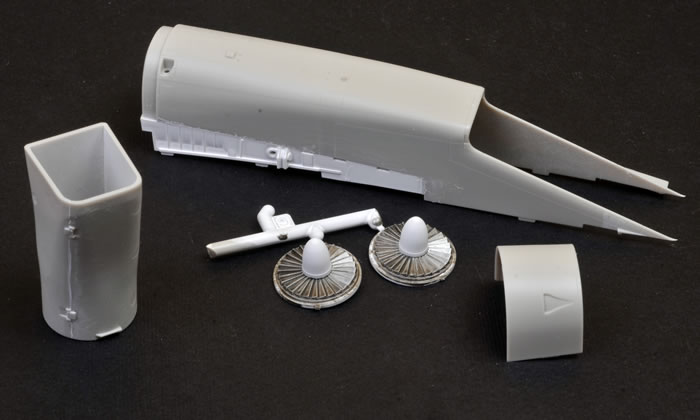
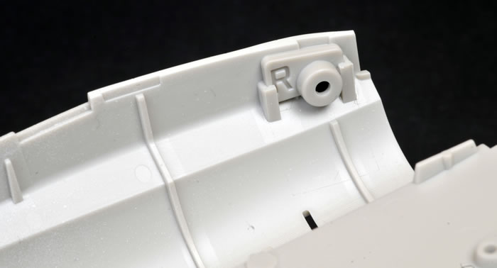
Tamiya helpfully labels the intake assemblies R and L for Right and Left.
The intakes fitted well after being pressed firmly in place. Irwin clamps were used to keep the pressure on as the glue set.
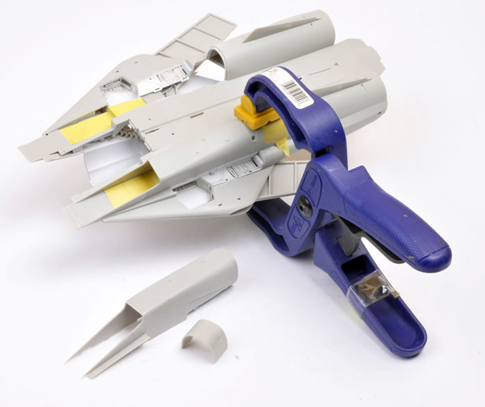
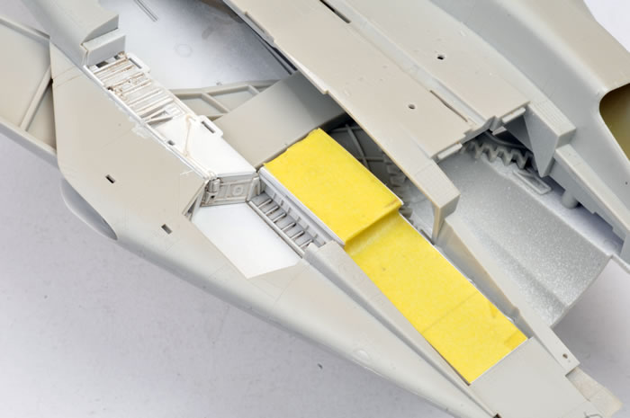
The white painted intake ramps were masked at this stage. This was easier than fiddling inside the intakes later on!
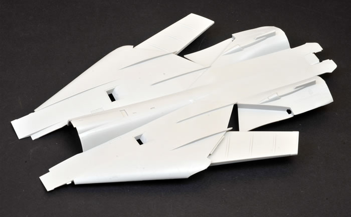
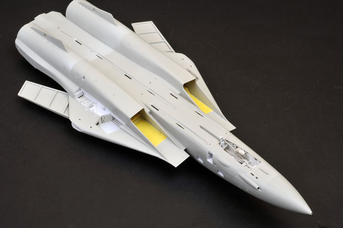
The main fuselage section, upper view.

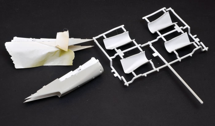
The nose and main fuselage are ready to be brought together.
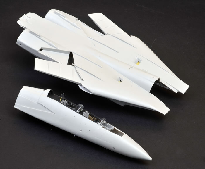
Fit between the nose and the main fuselage pancake is flawless.
The nose undercarriage bay and lower nose panel...
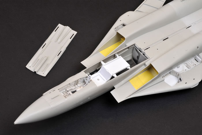
...which, naturally, fits perfectly!
A view from above.
The horizontal stabilisers are made up from two parts each and are held in place with polythene caps.
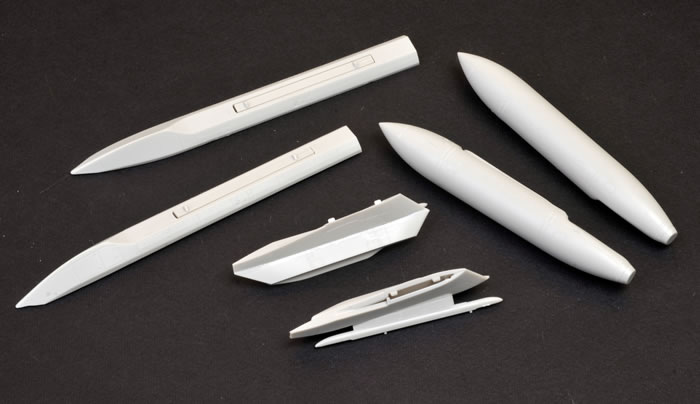
Pylons and tanks for Weapons Option III in the instructions.
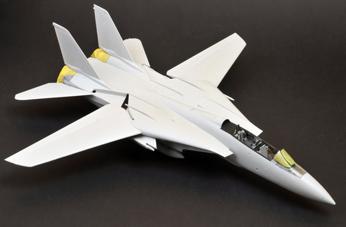
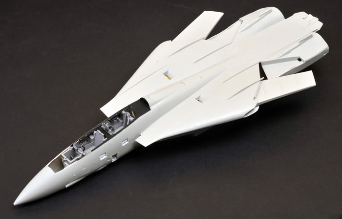
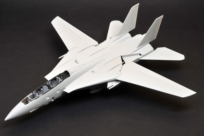
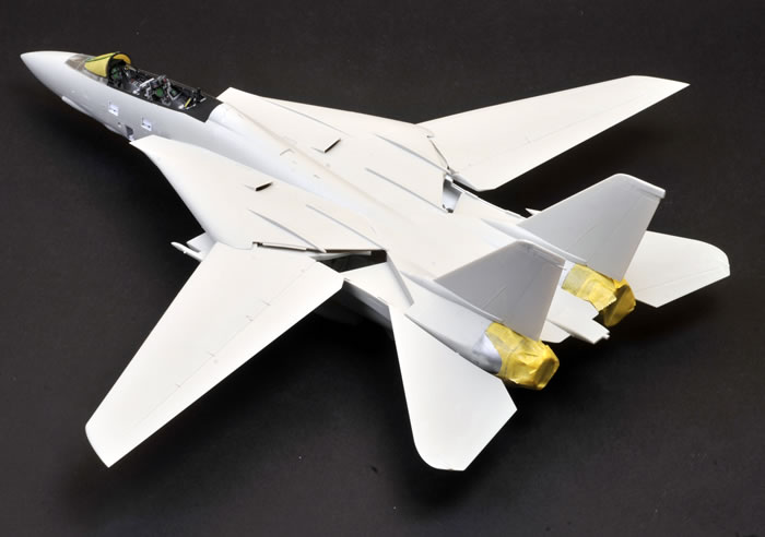
The wings and horizontal stabilisers are being test fitted here but will be removed for painting.
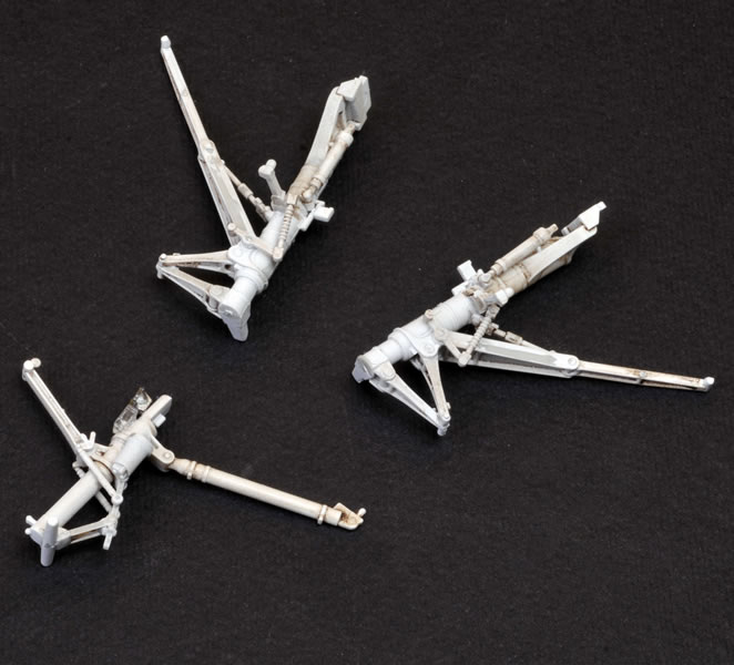
Nose undercarriage parts awaiting assembly.
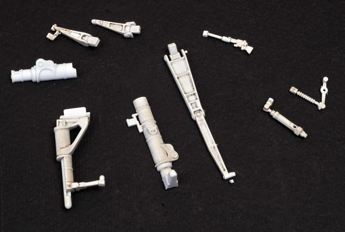
The completed main and nose undercarriage legs. I'll be re-painting and re-weathering these.
Exhaust parts painted and awaiting assembly.
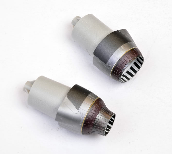
Burner cans assembled - one open and one closed. I'll be tidying up the paint on these too.
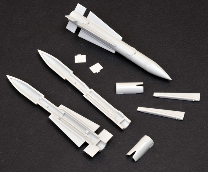
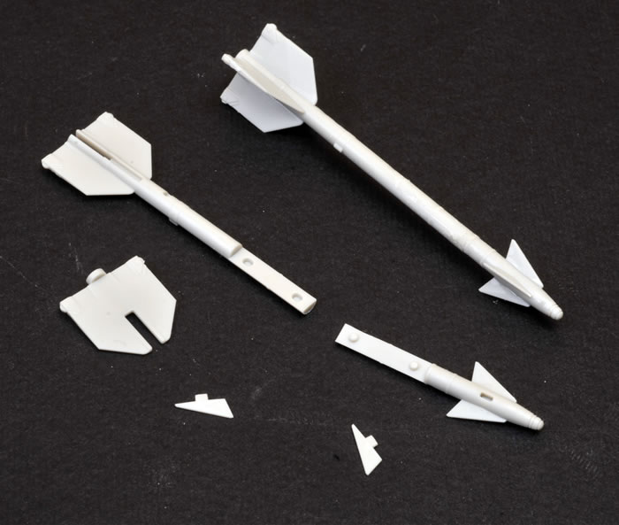
Phoenix missiles, components and assembled.
AIM-7E Sparrow missiles.
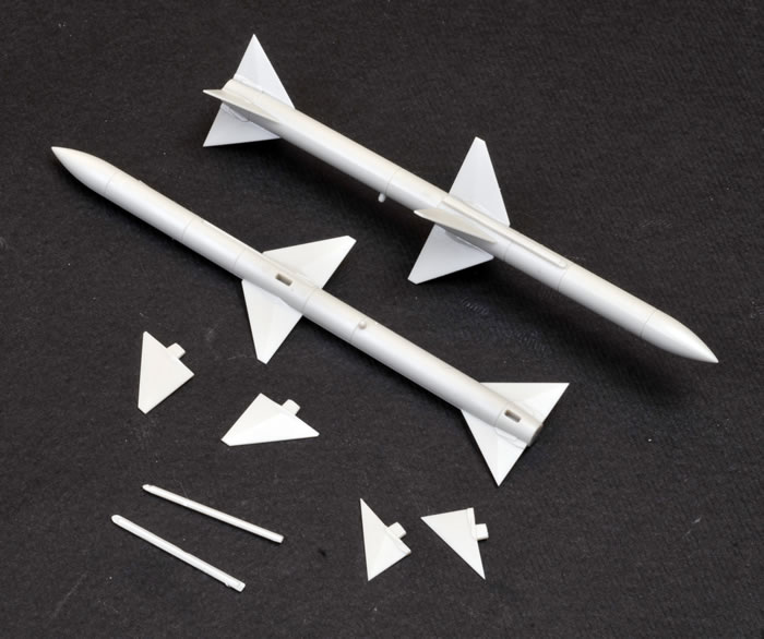
AIM-9G/H Sidewinders.
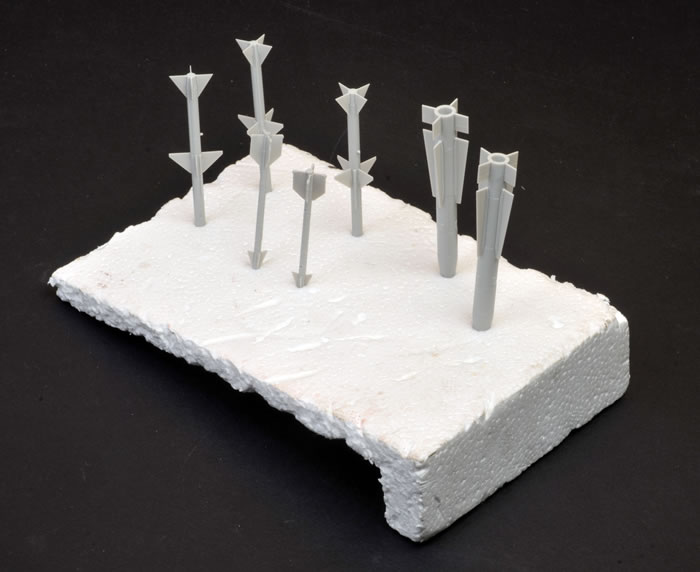
I used a chunk of styrofoam to hold the missiles while painting them with Tamiya White Primer, straight from the spray can.
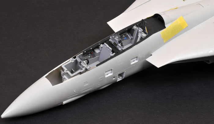
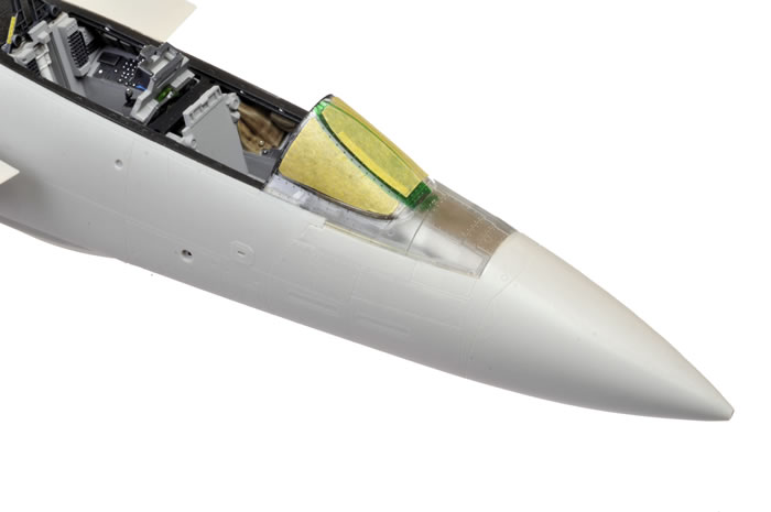
The windscreen is moulded with a section of the upper nose. The windscreen has been masked here in preparation for painting.
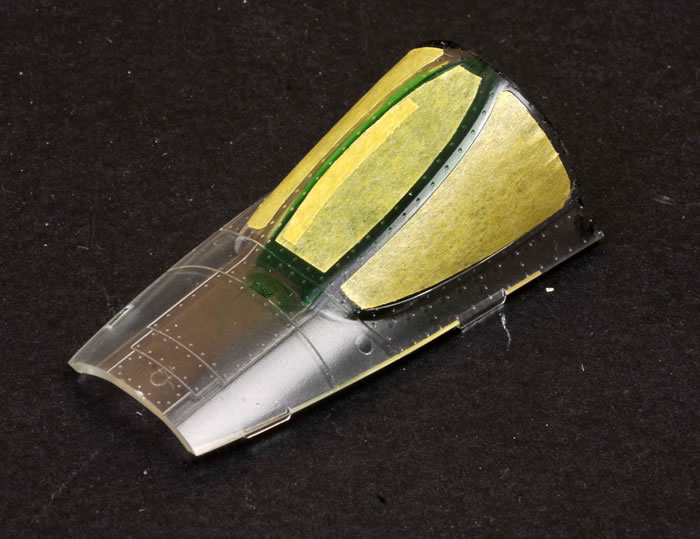
The cockpit is about to be sealed up - temporarily - for painting. The pilot's instrument coaming is in place.
The fit of the windscreen is perfect.
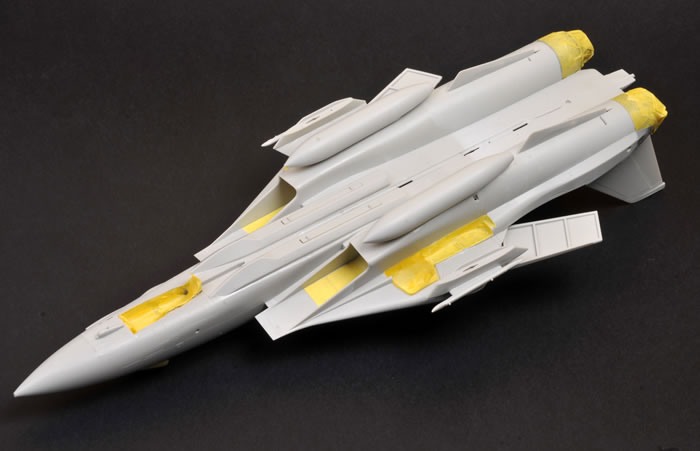
Undercarriage bays and burner cans have been masked with Tamiya tape.
One more test-fit of the wings and horizontal stabilisers. I haven't fitted the small avionics parts yet.
Next time we'll be showing you the finished model. |
 Home
| What's New | Features | Gallery | Reviews | Reference | Resource Guides | Forum |
Home
| What's New | Features | Gallery | Reviews | Reference | Resource Guides | Forum |