|
Squadron/Czech Model 1/32 scale
T-33 Shooting Star
by Mike Millette
|
Lockheed T-33 Shooting Star |

Czech Model's 1/32 scale T-33 Shooting Star is available online from Squadron.com
 Most of my choices of modeling subjects are based on paint schemes. Colorful markings or unique camouflage schemes are an almost certain draw. The T-33 was built in large numbers with around 7000 built. It also served in more than 30 air forces from 1949 to the present, not to mention plenty in civil service. Most of my choices of modeling subjects are based on paint schemes. Colorful markings or unique camouflage schemes are an almost certain draw. The T-33 was built in large numbers with around 7000 built. It also served in more than 30 air forces from 1949 to the present, not to mention plenty in civil service.
When Squadron/Czech Models released their 1/32 T-33, the opportunities for cool paint schemes were just about endless.
Brett provided an in box review on this kit a short while ago, so I won’t repeat any of his excellent review.
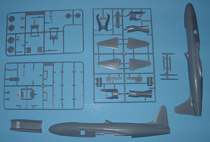
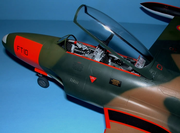
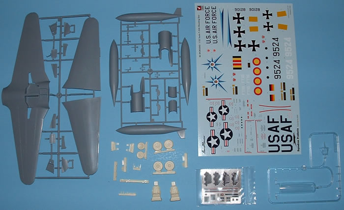
My initial look at the kit revealed some very nice features, nice enough in fact that I decided to build the kit entirely out of the box. Surface texture is smooth and shiny; though running your hand over the surface reveals some minor surface roughness in a few areas. The surface texture is nothing to be concerned about under a flat camo scheme, but definitely something that would need to be polished out for a clean bare metal finish. Panel lines are crisp and even, and the kit appears to be nicely in scale, with a few minor issues. The cockpit looks nicely detailed. I really like the combination of plastic, PE & resin parts.
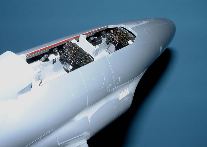
There are some notable areas that could use some help though. The footwells under the instrument panels are absent as is the heavy internal framing of the large canopy. Other missing details throughout the airplane emerged as the build progressed, suggesting that the out of the box plan might not be as satisfying as I expected. In the end I decided to build two T-33s; this first one being almost out of the box, the second, upcoming build will incorporate a number of hand done modifications and some of the aftermarket upgrades that are being developed to enhance the kit.
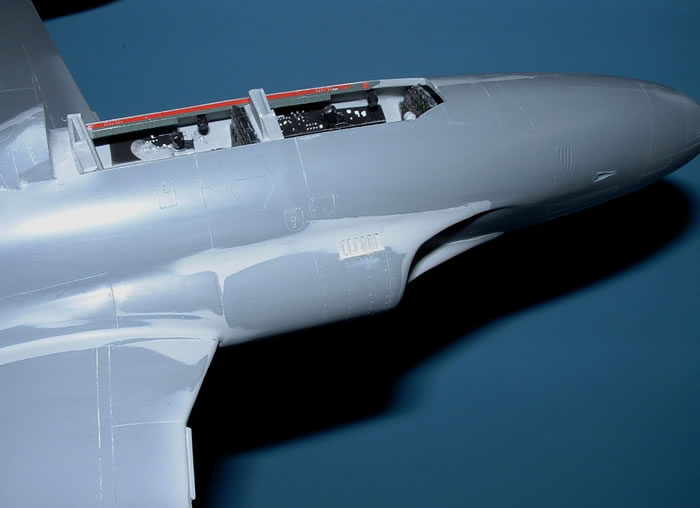
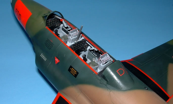
Not surprisingly, the build starts with the cockpit. The cockpit builds up easily, with a nice combination of parts that are appropriate for their application. The raised detail is nice & sharp, in fact it looks much crisper than Czech Models 1/32 F-80C. Resin parts are supplied for the seats, throttles, one instrument cluster, a sidewall mounted handle, canopy release mechanism and two oxygen regulators. The PE parts for some the two main instrument panels, instrument side panels, data plates and sidewall document holders look great and fit perfectly. One area that the modeler needs to be careful about at this point is the placement of the aft instrument panel in relation to the back of the forward seat. The canopy opening actuator needs to fit between the two. Placement of the seat ejection rails into the slots in the floor and placement of the aft instrument panel just aft of the locator tabs will not leave enough room for the canopy actuator. Either the seat needs to move forward or the instrument panel needs to be moved a bit aft, or a combination of both will allow the space for the actuator.
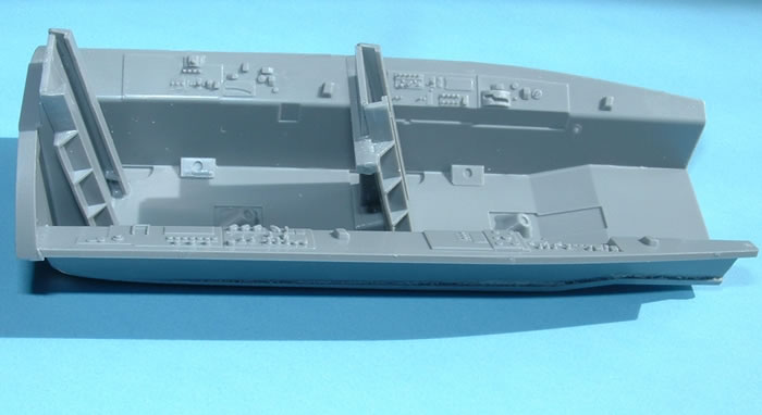
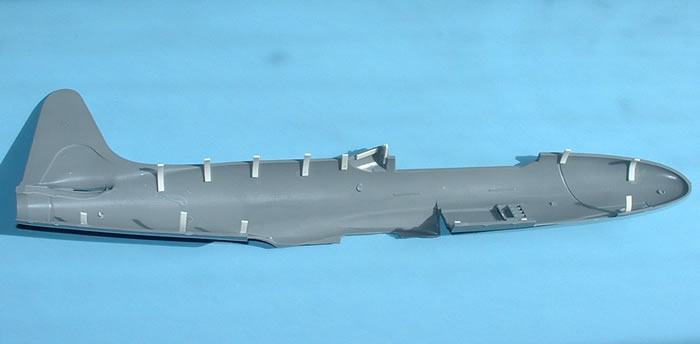
As with a number of limited production kits, there are no locator pins to help you line the major pieces up. I found fuselage left-right fuselage alignment to be helped significantly by gluing in some tabs along the upper and lower spines. Even with tabs glued in, it still takes a little persuasion to get the left & right halves to line up vertically, but it’s fairly easily done.
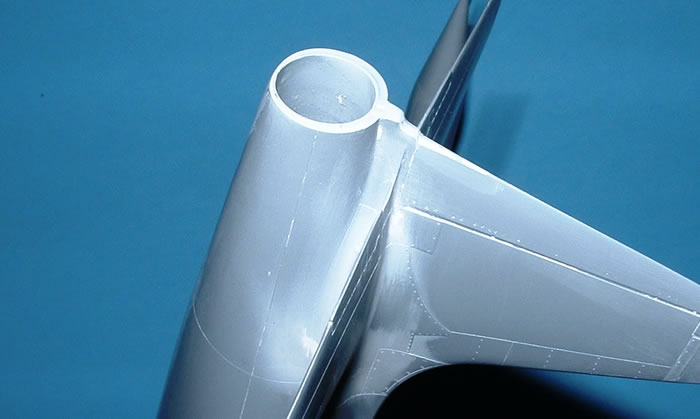
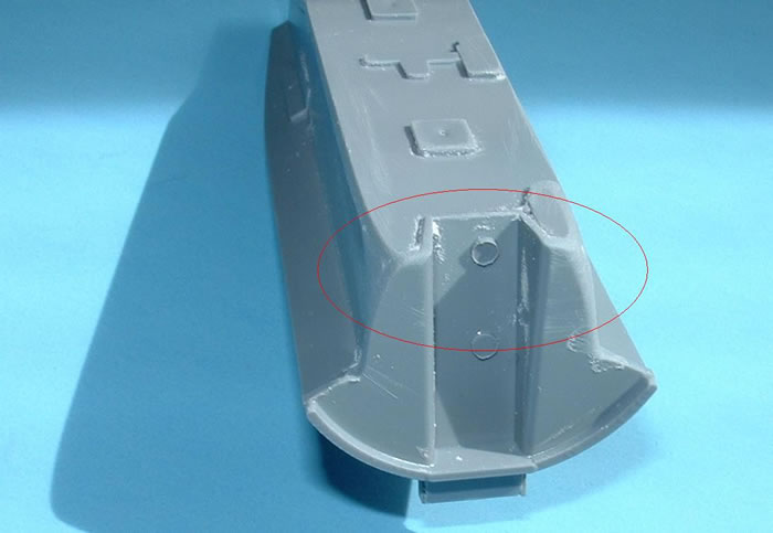
During assembly of the fuselage, another issue emerged. In all of the photos I’ve seen of T-33’s the engine exhaust sticks out from the end of the fuselage. When I installed the tailpipe assembly in the provided slots, it sat flush with the end of the fuselage. I tried moving the exhaust pipe aft, but there was no way the fuselage would close if I did that. As it was, I still ended up with a gap at for the last ½ inch or so of the lower fuselage. I’ll have to rethink this area for my take two build. The trailing edge of the vertical stab is a little thick as well. I sanded it down to provide a more realistic trailing edge.
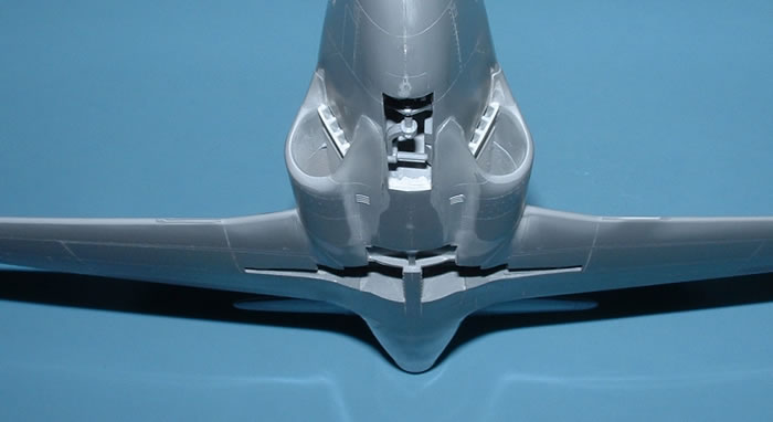
The intake splitters are the next assembly step. As molded, these parts have a tab on them that results in a step, in the inboard inlet surface, that isn’t on the real aircraft. The tabs need to be clipped off and carefully aligned to result in a smooth surface. The intake trunking also needs some work. The T-33 kit utilizes the inlet trunking from the F-80 kit with an insert for either inlet to account for the longer fuselage. The instructions would have you glue parts C14/C13 to C12, and parts D9/D10 to D7/D8. I would suggest gluing D9/D10 to C13/C14 first and then gluing the assembled outer trunking parts to part C12. This allows the modeler to putty and clean up the joint between C13/C14 and D9/D10 insert trunking pieces before everything is trapped inside the inlets.
The next issue to tackle was the nose gear well. The kit instructions would have you assemble the nose wheel well in step 8, but not install the nose gear strut until step 23. The problem with this approach is that the way the nose wheel well is assembled, the nose gear strut trunion (the cross piece at the top of the strut) cannot be installed in the wheel well once the well is assembled. I installed the gear strut trunion in the appropriate slots in parts C9/C10 as the wheel well was being constructed, but didn’t apply any glue. This way the strut could be rotated up into the wheel well to avoid damage during the rest of construction and then rotated down and glued in place prior to completion.
Back to the inlets, they had some interesting fit issues when attached to the fuselage. First the resin vents were carefully separated from their mold blocks. They were then carefully inserted into the appropriate slots in the inlet exterior pieces (D7/D8) and superglued in place. They fit pretty well.
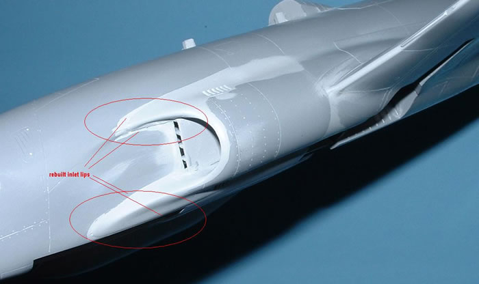
Where things got a bit dicey what when I tried to install D7/D8 to the assembled fuselage. They wanted to sit proud of the wingroot/aft inlet area and did not want to fit down into the slots in the forward fuselage, even with the help of liquid glue. I trimmed the inlet lips a little and that helped some, but the inlets still required a good bit of persuasion to get them to fit. I think the problem is that the alignment strap at the aft ends of parts D9/D10 interferes with the outer inlet pieces fit.
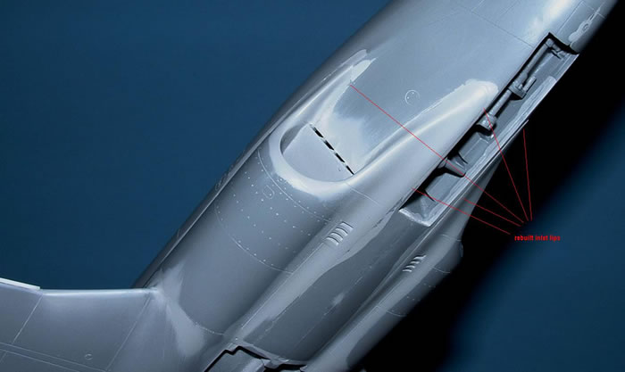
I’ll work on that in Take Two of this article, and we’ll see how that works. In any case, it took a bit of work to get the inlets to fit and a fair amount of superglue and Mr. Surfacer to fill the gaps. As a result, the lap joint detail around the inlet lips was lost in the resultant sanding. To restore this detail, I laid out strips of tape around the inlet lips and then sprayed several (8-10?) thin layers of Mr. Surfacer onto the inlet lips. After removing the tape and some careful sanding, the subtle lap joint detail was restored.
Another fuselage/inlet assembly issue resulted from the interference of the cockpit and inlet pieces. With the cockpit in its correct location, the aft lower corners of the cockpit demonstrated an interference with the inner inlet piece (C12). I found that if I sanded the lower aft corners of the cockpit tub, I could get the intakes to fit right.
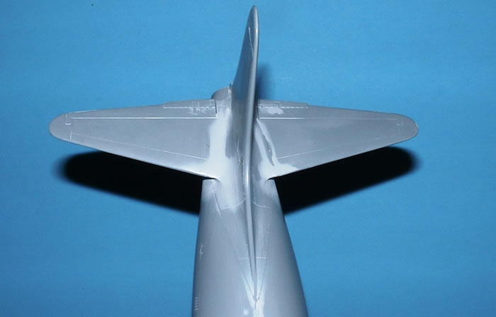
Once the fuselage was all together, I turned my attention to the horizontal tail. The horizontal tail pieces have a tab and slot feature for positive alignment, but there were still some gaps that had to be filled once the stabs were installed. A little superglue & Mr. Surfacer, and the joints looked great.
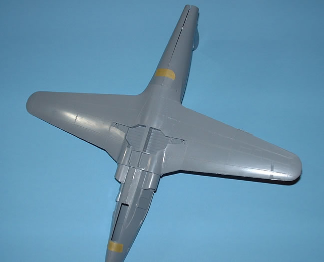
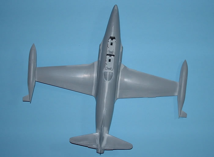
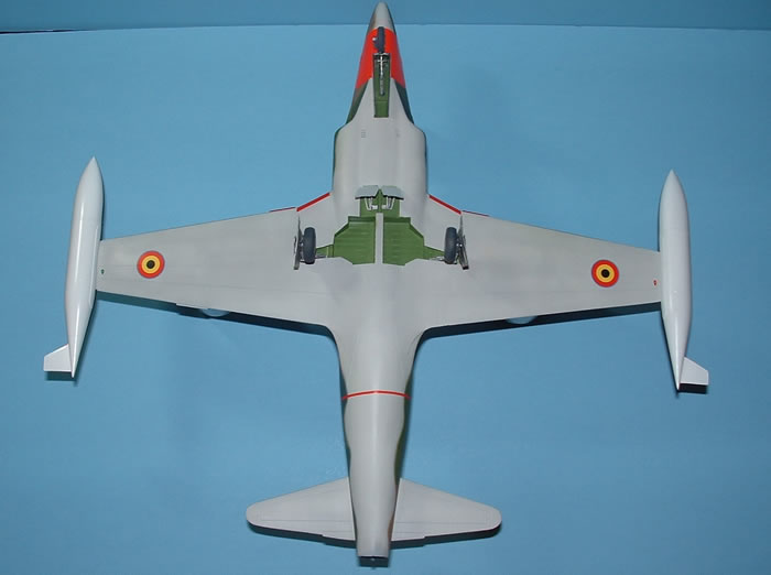
Once all of the fuselage pieces were together, I turned my attention to mating the wing to the fuselage. The wing consists of one lower surface part with the two mating upper wings and a couple of pieces, which make up the outer wheel wells. The wheel wells go together without any problems and fits perfectly in the bottom wing. I had to trim a little of the upper wing pieces where they pass over the wheel wells, but a little liquid glue got everything where it needed to go.
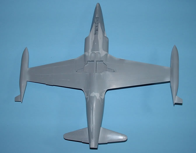
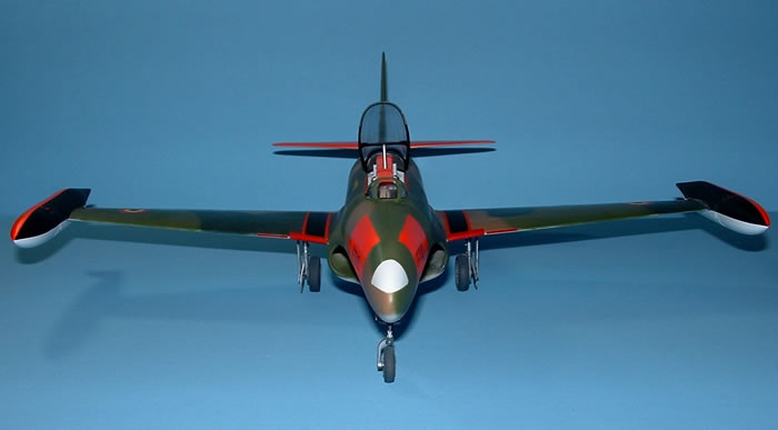
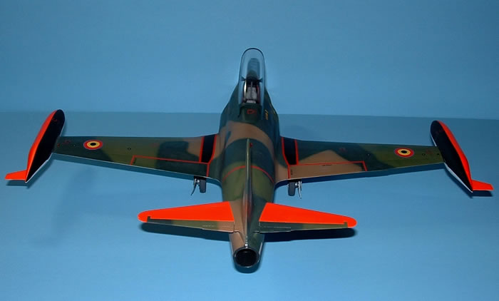
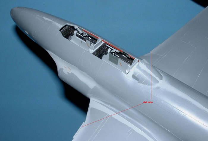
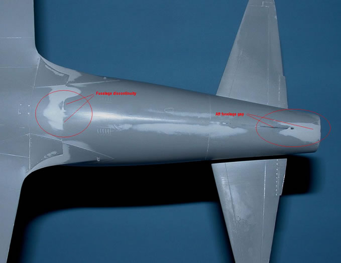
The wing fit well to the fuselage, with just a minor amount of Mr. Surfacer being used, but something odd emerges. On the kit, the fore-to-aft wing joints are straight lines. In the instructional drawings and even more important, in photos, the wing root joint is a subtle but very clear curve. This caused me some issues during the painting stage that I’ll address later. Where I just had to diverge from my OOB plan was at this point. The inboard leading edge of both wings (on many but not all airplanes) has a piece of angle iron attached to it. I belive it’s intended to cause the inboard portion of the wing to stall first so that the ailerons are still effective. In any case, they are pretty prominent and on some aircraft (the one I was modeling in particular) they are even painted red. Id say check your references to see they’re on the aircraft you’re modeling. I added some plastic strip stock to simulate this item. The other issue is the joint between the aft end of the center wing where it joins the aft lower fuselage. Despite some serious persuasion, the aft fuselage still stands proud of the lower center wing surface by about 2 mm. It took a good bit of sanding and Mr. Surfacer application to smooth this out. Fortunately the softness of the plastic makes short work of this problem, but it was a bit of annoying.
The tip tanks went together relatively easily, even without the internal structure. These parts actually have alignment pins. They installed onto the wingtips easily as well.
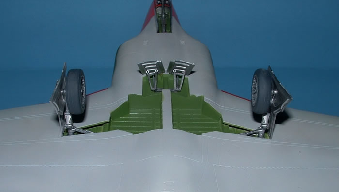
Once all the major components were assembled, I added the gear and speed brakes. These were attached after the wheel wells and speed brake wells were painted. The wheel and speed brake wells seem reasonably shaped, but a bit light on detail. For this build, these areas were kept stock, but in take two, some after market resin will be used to dress this area up. The wheels & gear struts assembled reasonably easily, the only issue I had was the flimsiness of the nose wheel strut. If I had to pick one “necessary” bit of aftermarket, cast metal struts would definitely be the ticket here. I had to be very careful when setting the model down once the gear was glued in place.
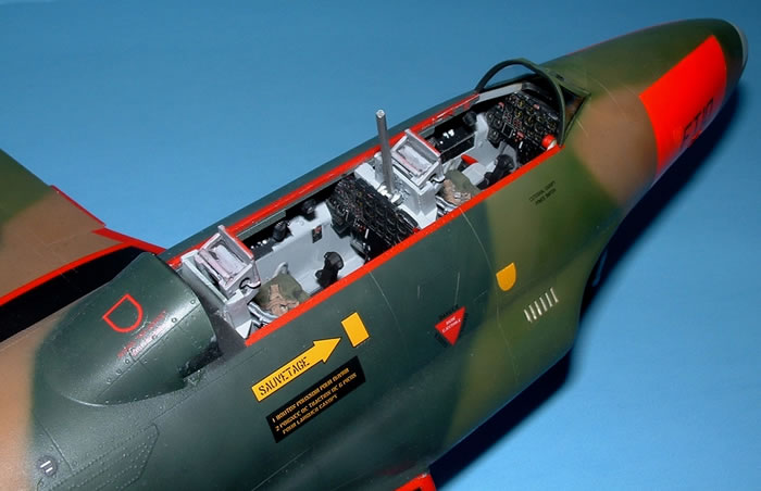
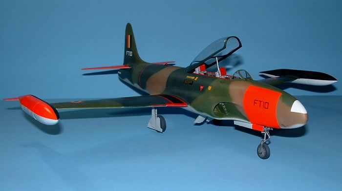
The last parts to add, again, after painting were the windscreen, canopy and formation lights. These are absolutely beautiful parts. The huge canopy is clean, clear and distortion free. Unfortunately, the size and clarity of the canopy highlight a couple of issues that let the beautiful canopy down. To start with were the cockpit sills. On the real aircraft the sill is something like 3-4 inches wide and flat, and just to make it more obvious, they are often painted red. The cockpit sills on the kit however, come to a sharp edge at the top. I wondered about sanding them flat, but at this point I had already glued the PE and resin parts in place. I struggled with whether to tear everything apart and fix the sill on this build. In the end I stuck with my almost OOB build, but I will definitely address this in Take Two. Along the same lines, the canopy on the real airplane is some 7 feet long, and cantilevered from the aft hinge point. In order to maintain structural rigidity, the frame on the real aircraft has some considerable thickness to it, matching the cockpit sill. The kit canopy frame is the thickness as the clear portion of the canopy. Many real aircraft also have an interior canopy bow that can be clear or metal. It’s used to attach a blind flying hood to. This is another item that will have to wait for Take Two. What did need to be fixed for this build is the thickness of fairing aft of the canopy. The fairing is too wide for the canopy hinge tabs to fit on either side of it. After a few fittings, the canopy developed some stress cracks, which aren’t visible in the photos, but unfortunately were visible at certain angels in person. I also broke one of the tabs off, which needed to be re-glued and the crack smoothed and repainted. Ultimately, I shaved plastic off of both sides of the fairing so the canopy fits better. The stress cracks also don’t show up as obviously either… Whew!
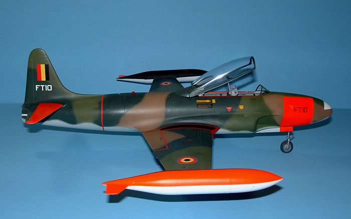
Squadron/Czech Models have included decals for thee different aircraft with the kit, one USAF, one Luftwaffe and one Belgian Air Force (BAF) aircraft. The decals are excellent, all in register. Very little carrier film surrounds the markings, but a little Solvaset and the decals just disappear. One thing to mention here, the kit markings include a yellow stripe for the Luftwaffe aircraft. In reality this stripe is really day glow orange, the same as on the tip tanks. Over time, this color fades to a scruffy yellow color, so if you do use the decals, the tanks should probably be a matching scruffy yellow color as well, otherwise the stripe should be masked and painted the same day glow orange color as the tanks.
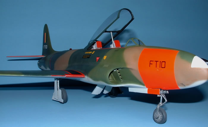
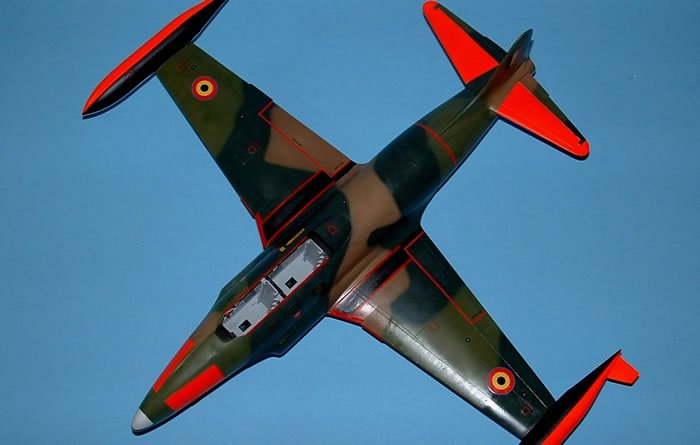
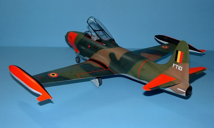
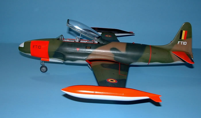
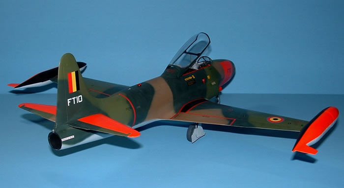
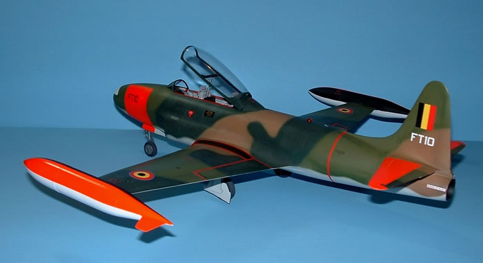
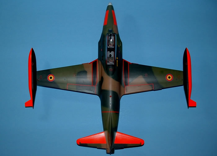
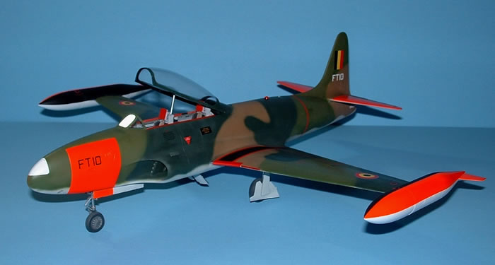
For me, deciding on which paint scheme I wanted to model took more time than building the kit. There are literally hundreds of schemes to choose from. Ultimately I came across a photo of a BAF aircraft with the kind of color scheme that just grabs my attention. A cool four color (including the lower surface) camouflage scheme, totally compromised by huge swathes of day glow orange, white, black and red trim… it was just too cool to pass up. The model was painted with a selection of Model Master colors. Real BAF T-33’s all look really well taken care of, so a minimum of weathering was applied.
As I mentioned above, the kit panel line layout caused some issues with the paint scheme layout. The wing root was the issue. Initially I laid out the wing walks following the kit panel lines. This is made more obvious by the red trim on either side of the wing walks. I left it this way for a little while, but the photos I looked at, the more obvious it seemed that it couldn’t have been laid out that way on the real aircraft. In the end, I sanded the aft end of the walkway back, repainted the wing walk to follow the real curvature of the wing root and reapplied the red decal trim. It looks a lot better that way, but I think the curvature is still a bit deep. I’ll have to give this some thought for Take Two.
That’s about it. With all the various issues that I mentioned above, one might get the impression that I didn’t like the kit, and that’s just not the case. Yes, there were some funky construction issues to address, but the softness of the plastic and creative use of Mr. Surfacer worked to sort out most of the fit issues.
Even with the various hassles, the basic construction only took ~ 10 hrs. The low parts count helps a lot! Painting actually took about twice as long as construction, part of that, of course was due to deciding what to do about the wing walks. My enthusiasm for the kit hasn’t been dampened in any way and I’m definitely looking forward to a second build.
With a little care and modeling skills in mind, I would highly recommend this kit.
Models, Description and Images Copyright © 2010 by Mike Millette
Page Created 26 August, 2010
Last Updated
31 August, 2010
Back to HyperScale
Main Page

|
 Home
| What's New |
Features |
Gallery |
Reviews |
Reference |
Forum |
Search
Home
| What's New |
Features |
Gallery |
Reviews |
Reference |
Forum |
Search