Airfix 1/48 scale TSR.2 Main Gear Legs
Correcting the Splay Angle
Revised Version
by Steve Naylor

HyperScale is proudly supported by Squadron
This is the second (updated) version of the article which was first posted on Hyperscale, on 13 February 2009. Originally, the 'corrected' gear leg angle chosen (15 degrees) was based on information available to the author at the time, offered with certain caveats. Subsequent to some online debate concerning this angle, the author eventually managed to visit a surviving example in order to ascertain the correct angle. The result of the visit has been posted as Technical Note elsewhere on Hyperscale and so the following article has been edited to reflect the new information (that the angle is actually 18 degrees), albeit that the accompanying photographs are the original ones and so obviously show the original degree of correction. In this second version, where necessary to aid the reader, any comments or notes on the voracity of the original text will be included in square parentheses, i.e. [ ].
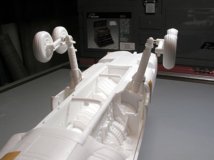
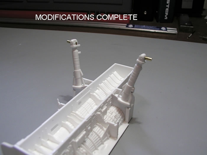
Now I know what you are thinking, 'What's the problem with the main gear leg angle?' Well I think there is one, as I shall explain presently, though whether or not you agree with me, or think it worth the effort to correct, is another issue. Nevertheless, having run it past Brett, he asked if I would write-up my solution which I offer for your edification, the practical result of which is shown above.
Background
Hard to believe I know, but the Airfix 1:72 TSR.2 kit came out back in early 2006, and whilst the full size aircraft is of great interest to me, that kit was unfortunately in the 'wrong' scale (i.e. not 1:48!). As a result, I did not pay too much attention to the various reviews and build-ups which subsequently appeared, but the one thing which did attract my attention, was the outward splay angle being achieved, of the two main undercarriage gear legs. This angle always looked a little suspect to me (i.e. far too splayed), the net result being that the smaller TSR.2 kit always seemed to have a rather 'ruptured duck' look in my opinion, when compared to images of the aircraft and my own sight of XR220 at Cosford. However, not having had access to the 1:72 kit, and since no one else seemed to be commenting on this aspect anyway, I just assumed that the leg location provided in that kit was poor, allowing an unnecessary degree of freedom.
So, having pre-ordered and after a year of waiting, January 2009 saw the new Airfix 1:48 TSR.2 kit finally arrive, to be eagerly examined by yours truly. As you can imagine, the first thing I looked at was the main undercarriage (the gear legs and their location), especially after seeing the exact same 'splay', in the 1:48 test shot build-up by David Francis, which appositely appeared in the January 2009 issue of 'Scale Aviation Modeller'.
References
So apart from how it looks, what is the correct outward splay angle, for the main gear leg on a TSR.2? Amongst the material I have collected for my build (a 'What-If'), I have two reference drawings to hand. The first, is the BAC General Arrangement drawing c.1964, which was reproduced in 'Model Aircraft Monthly' magazine a while back, and the second is the Mark Rolfe drawing from the November 2005 issue of 'Scale Aircraft Modelling'. In the former, the outward 'splay' of each main gear leg from the vertical, when viewed from the front, measures 17 degrees, whilst in the latter, the angle measures 15 degrees. [Originally, in my hast, I misinterpreted the BAC drawing and therefore stated that both drawings showed an angle of 15 degrees. Despite this anomaly however, both still illustrate a discrepancy with the kit angle].
That there is a problem, is also partly corroborated by a 'third-hand' source I have, which came from 'Mike' in a thread on 'The Jet Age' Forum, here on Hyperscale (18 January 2009). Mike said that in the book "TSR-2 Phoenix or Folly?" by Barnett-Jones, the maximum undercarriage track on the TSR.2 is stated to be 13ft 6in (or 85.7mm at 1:48). When this distance (tyre centre to tyre centre) is measured on the two reference drawings mentioned above, it scales out at 13ft 3ins or 13ft 4ins (so pretty consistent). The maximum track would presumably be with the gear leg oleo fully extended (i.e. in flight, gear down), whereas the reference drawing(s) show the gear depressed on the ground (when the track measurement would be slightly less).
In order to attempt to remove any doubt therefore, I paid a visit to the RAF Museum at Cosford (2 March 2009), in order to examine TSR.2 'XR220'. Details of this visit can be found elsewhere on Hyperscale, sufficed to say that the observed angle of splay of the main gear leg, turned out to be 18 degrees. [The original article of course, continued in ignorance of this fact and proceeded to modify the kit's gear legs to the 15 degree angle. Whilst wrong in that respect, the method is still valid for the correct angle].
Kit Before Modification
So what of the kit's main undercarriage, its location method and 'splay'? In order to find out, the first thing I did was to dry-assemble the fuselage/nosewheel bay/gear & weapons bay/gear legs arrangement, including the front wheels and the mainwheels (on their bogie units), to see how all this looks on the 1:48 scale version. Well the first thing to say, is that the location method between the gear legs (Parts 8B and 9B) and the gear & weapons bay (Part 4B) is very precise (though I did have to use some folded paper slivers to ensure a tight 'jam' fit whilst taking the measurements and photographs). This is an arrangement which does not allow for any noticeable latitude, so what is the resultant angle?
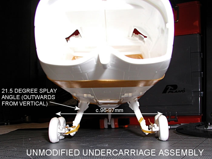
With the kit aligned on my cutting mat's grid, I checked the angle by sight, using a draughtsman's adjustable set square at right angles to the model's centreline (the gear leg is at a compound angle, so direct contact measurement is not possible). In confirmation of my suspicions, the angle on the Airfix 1:48 TSR.2 measured 21.5 degrees from vertical, as opposed to 18 degrees [15 degrees originally], i.e. 3 degrees too much [6.5 degrees originally]. To double-check, I also measured the kit's undercarriage track and on my Airfix 1:48 TSR.2 at least, this measured c.96-97mm, as opposed to c.86mm, equating to a real-life distance of 15ft 1.5ins! Taken together, I believe that the main undercarriage angle on this kit is therefore wrong and is the reason for the unsatisfactory splay angle exhibited in kit build-ups in both scales (kit design being substantially the same in both cases).
[Although third-hand information, the author now understands that Airfix actually used 21 degrees as the gear leg angle, based on 'production drawings'].
The Solution
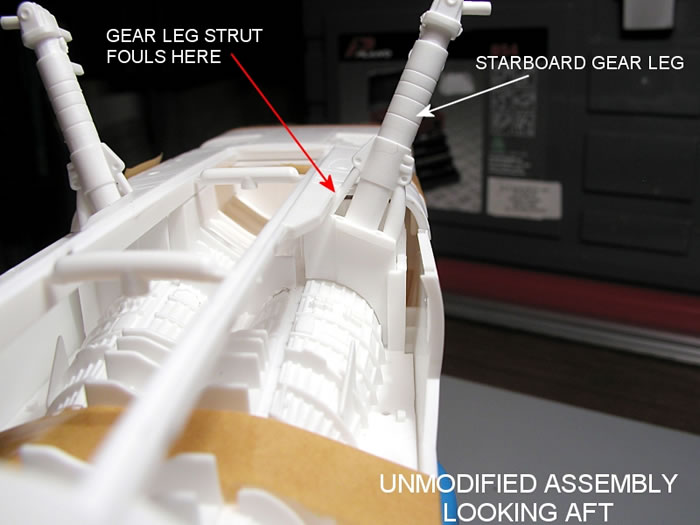
Enough criticism, so what can be done about it? Well, had it been possible, by far the simplest solution would have been to lean the whole gear leg (Parts #8B or #9B) inboard by the necessary 3 degrees [originally 6.5 degrees] and fix it in that position somehow. Unfortunately, the inboard reinforcing strut at the top of the gear leg, already fouled the inner edge of the gear bay opening [on my sample], so that was not an option.
After some thought, it seemed certain that the necessary rotation would have to occur near to that opening, so that the change of angle did not increase the existing contact any further, and if possible, reduce it.
In the next images, you can see the fixing arrangement in more detail and the unaltered starboard gear leg.
Cutting Plastic
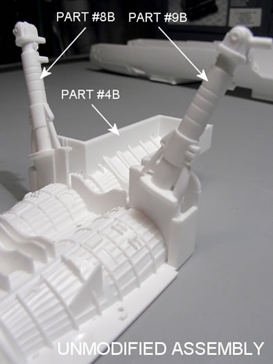
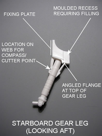
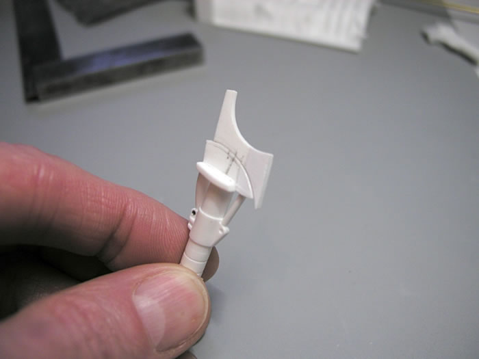
The following, is a description of what I did to correct the gear leg angle. Before starting though, there are a couple of things to say. First; is to familiarise yourself with the gear legs and their orientation. The front face of the Starboard leg is shown above, and the leg is angled rearwards from what I am calling the 'fixing plate' at the top. Confused? Well just remember that the rear of each gear leg has the pair of location projections at the lower end, for the oleo scissor link (Parts #10B or #11B). Second; there is a moulded recess in the front face of the fixing plate (as indicated above). This needs to be filled (made flush) to the same level as the rest of the plate. This will both aid the cutting in the next step and allow for strengthening of the resultant joint later. To fill this recess, I used 0.5mm sheet stock and liquid cement, the excess being trimmed to the existing profile when dry and the front face sanded flat (sorry, no picture of this step).
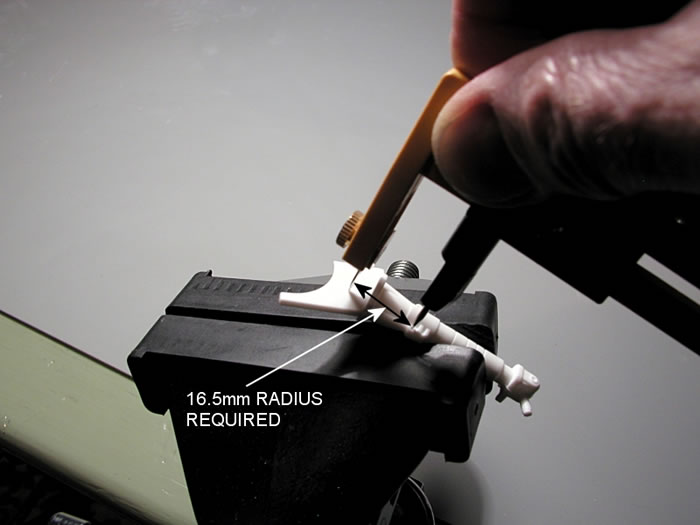
To create the point (or arc) of rotation for the gear leg, I used a small Olfa circle cutter (though a pair of drawing compasses with steel points in both tips, would also do the job). Setting the Olfa cutter to a radius of 16.5mm (any less, and you'll be cutting through part of the angled 'flange'), I placed the point of the cutter into the moulded fixing detail, on the outer web at the upper end of the gear leg (see image above and below).
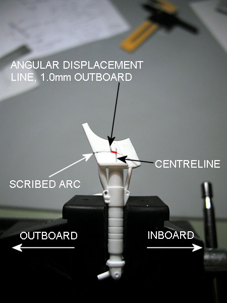
Using that point as the pivot, I scribed an arc at that radius, across the front face of the fixing plate, to facilitate marking-out. Then, using the end of a steel ruler and a scriber, I marked a line on the fixing plate, perpendicular to the flange at the top of the gear leg, in-line with the centre of the leg, so that the line bisected the arc. Now you need to mark the necessary angular movement required. If you do the math(s); for a radius of 16.5mm, the circumferential distance required to produce 3 degrees of rotation [originally 6.5 degrees], is near enough 1.0mm [originally 1.9mm]. Setting this distance on a pair of compasses (the difference between arc and chord length at this point and scale, is negligible), I marked this distance from the previously marked centreline/arc intersection, on the stub-axle (outboard) side of the arc. The resultant marking out, should look like the image below.
Once marked out, I then positioned the Olfa cutter as before and used it to carefully cut completely through the fixing plate, leaving it separated into two parts (as below).
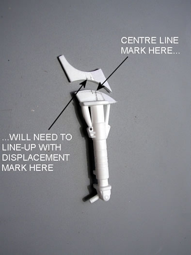
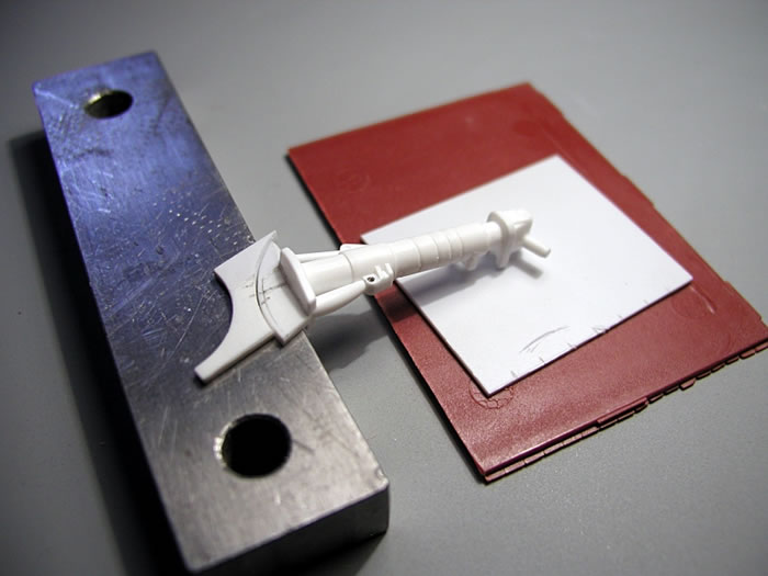
After some light cleaning up, its just a simple matter of reassembling the two parts, this time realigning them such that the centreline mark of the gear leg, now lines up with the second (outboard) displacement mark, which has the effect of rotating the leg inboard (which is what we want). To be sure that the rejoined fixing plate remained in line during gluing (to maintain the rearward 'set' of the gear leg), I set the assembly up on a block as shown below, and applied liquid cement. After a few seconds, I pressed the two parts together to ensure a good bond and left to set (the steel block I used, also ensured that the components did not stick to it!).
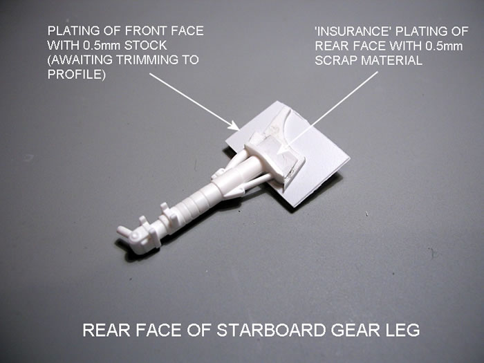
In theory, a well-glued joint here would probably have been sufficient, but for 'insurance' and to improve the appearance in the gear bay, I cleaned up the joint face (front and rear) and then 'plated' the front of the fixing plate with 0.5mm stock (as you can see, I also added some 'insurance' scrap material on the rear face as well - see below). Once that had set, I trimmed it to the new profile, removing any excess material and fettling the part until it fitted into Part #4B as before. Use the unmodified gear leg, to see how the modified one needs to be shaped to fit the location recess, engine duct curve and weapons bay sidewall. You may need to trim back the strengthening ribs, which run along the engine duct and vertical face of the weapons bay, to achieve a good fit (sorry, forgot to photograph the 'finished' leg at this point). Then repeat as necessary, for the second gear leg.
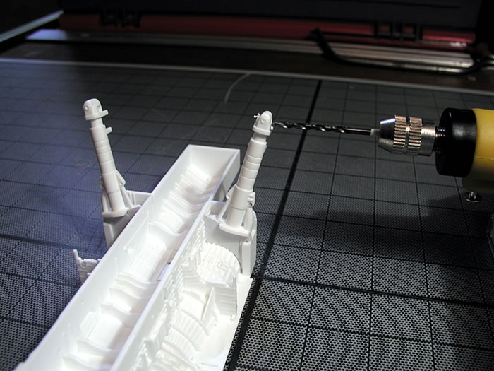
The final operation, is to replace the two stub axles at the bottom of each gear leg, which (when assembled in place) will now of course be 3 degrees below horizontal [originally 6.5 degrees]. First, I removed the offending plastic axles and cleaned-up the face on each one, ready for drilling. Then I glued the gear legs into their final position in the gear bay/weapons bay (Part 4B), along with the other major components in steps 10 and 11 in the kit's instructions booklet. Once dry, I temporarily stuck the resultant sub assembly to my cutting mat (aligned to its grid marks), using double sided carpet tape. Then, with an appropriate drill in the chuck, and with my mini-drill packed up to the right height for the new axles, I drilled right through each gear leg, at right angles to the weapons bay centreline (see below).
In my case, I decided to use 2.4mm diameter [3/32 inch] brass rod to provide the new axles, which is slightly larger in diameter than the plastic ones. Naturally, if you do this, the corresponding holes in the main gear bogie frames (Parts #12B and #13B) will also need to be opened-up slightly. Fixing with superglue, the excess brass material which I allowed to protrude on the inside of each leg, was filed flush as shown below.
Result
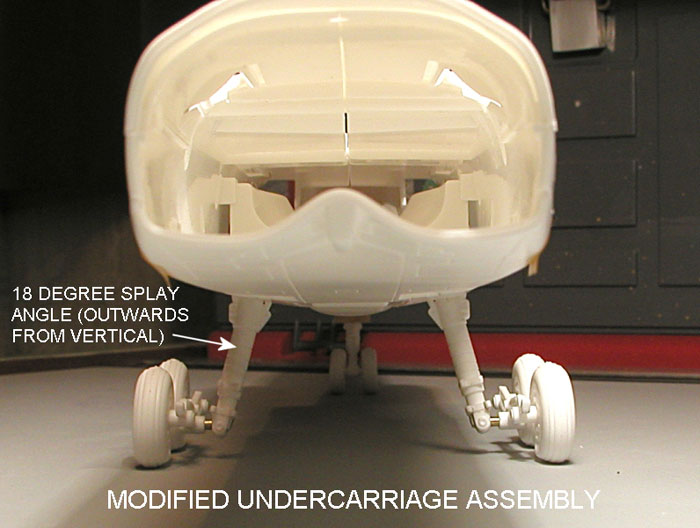
Reassembling the fuselage and gear legs as before, and set up for measurement, I checked on the result of all this work. In my case of course, it was 15 degrees (the actual angle achieved in the photograph below), but hopefully, the angle of your gear legs will now be 18 degrees! More important of course, is that the legs are symmetrical (mine were, thank goodness).
Checking the undercarriage track; well it was still a couple of millimetres or so too wide, even at 15 degrees splay, but this may improve once the whole assembly is finally glued in position, and also after I have tweaked the stub axle lengths to make them even.
So, was it worth it?
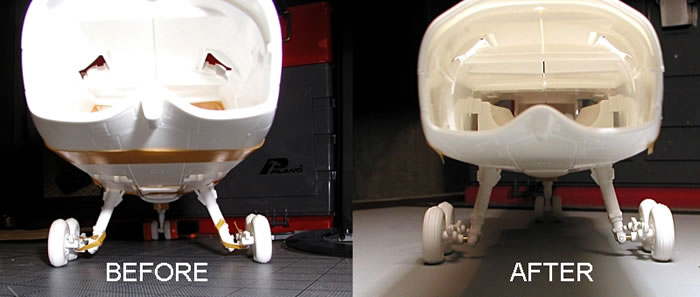
Well even if it is only 3 degrees correction (rather than 6.0-6.5 degrees) I still think it worthwhile, but then I used to be a mechanical engineering design draughtsman, which as a model maker, can be both a blessing and a curse. You will have to decide if it is worth it in your case. Looking at the last image below though, I feel it has made a considerable (and positive) difference to the 'sit' of the aircraft - more 'up-on-its-toes' than 'about to lay an egg', so if you think so too, I hope the above will be of help should you also decide to make this modification.
Finally, apologies to anyone who has completed this modification to the earlier 'standard', which I still think looks better anyway, and be comforted by the fact that I got caught out too.
Model,
Text Copyright © 2009 by Steve Naylor
Page Created 13 February, 2009
Last Updated
27 March, 2009
Back to HyperScale
Main Page |
 Home
| What's New |
Features |
Gallery |
Reviews |
Reference |
Forum |
Search
Home
| What's New |
Features |
Gallery |
Reviews |
Reference |
Forum |
Search