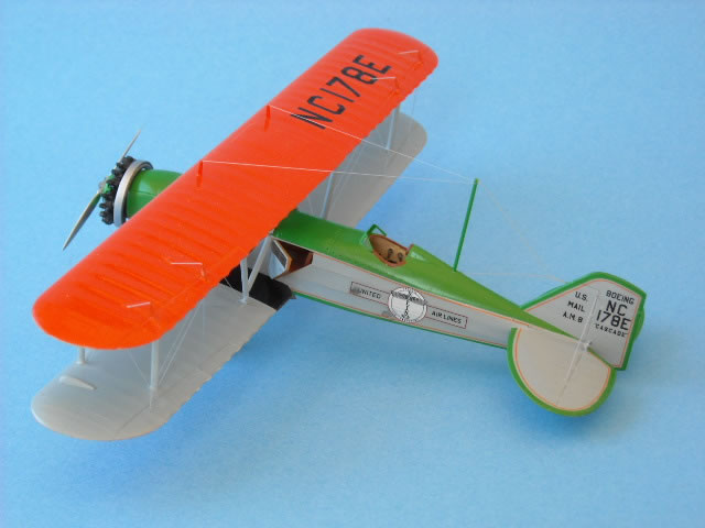
Czech Master Resin's 1/72 scale
Boeing 40B-4
by Bernie Hengst
|
|
Boeing 40B-4 |

HyperScale is proudly supported by Squadron
 The Boeing 40 is the best remembered mail and airline plane of the late 1920s and early 1930s. It was introduced in mid 1929. It served with eight American and one Canadian airline. A number of large corporations also used them for executive transports. The 81 Boeing 40s build in America and Canada made up the largest commercial plane order for airmail and passenger service up to 1930. The Boeing 40 is the best remembered mail and airline plane of the late 1920s and early 1930s. It was introduced in mid 1929. It served with eight American and one Canadian airline. A number of large corporations also used them for executive transports. The 81 Boeing 40s build in America and Canada made up the largest commercial plane order for airmail and passenger service up to 1930.
Airmail service started in the US on May 15. 1918 with Curtiss JN-Jenny trainers supplied by the US Army to the Post Office. The planes were flown by US army pilots. The 2,600 miles (4 128 km) from New York and San Francisco, via Chicago was opened between May 15. 1919 and September 8. 1920. Newly acquired Standard and surplus Liberty-engined Airco D.H.4M biplanes were used by the Post Office for the next eight years.
In February 1925 the Air Mail (or “Kelly”) Act was passed, providing for the transfer of the services to private companies. The contract for the Chicago to San Francisco section went to the Boeing Airplane Company and Edward Hubbard, and later to Boeing Air Transport (BAT).
Work started on twenty five Model 40As, powered by Pratt & Whitney Wasp engines of 420 hp. The Boeing Model 40As had room for two passengers, later the Model 40Bs, powered by Pratt & Whitney Hornet engine of 525 hp, and could transport four passengers.
This is another CMR kits that my friend, Bill Coffman gave me to build. The kit contains 75 beige and four clear resin parts, a fret with 45 pre-painted etched parts and two vacuformed windscreens. All the parts are packaged in a sectioned plastic bag, to avoid scratching and breakage of the small parts. A very nicely printed decal sheet for four diferent aircraft, a sheet with masks for the tail surfaces, four pages of instructions, four pages of colored painting and decaling instructions and four pages with information and black and white photos of some of the original aircraft, make up the remainder.
Construction started with removing the fuselage parts from the casting blocks with a saw and carefully cleaning them up with a fine file and wet sanding. Wearing a dust mask is a good safety precaution for doing these jobs. I was amazed at the quality of the resin castings, I found less than ten air holes and those mainly on the leading edges of the wings.
The parts were washed on soapy water and left to dry.
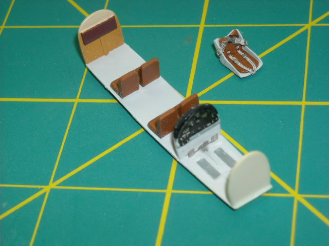
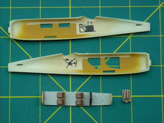
The inside of the fuselage halves and cockpit bulkheads were sprayed Model Master Radom Tan FS 33613. When dry the fuselage halves above the windows and the passenger bulkheads tops, as well as the complete cockpit area were masked and the parts sprayed with Humbrol Matt # 62 Light Brown. A day later the brown parts were masked and the floor in the passenger compartment and cockpit were sprayed Model Master FS 36 495 Light Grey.
While the paint dried during the next few days, I filled and wet sanded the leading edges of the wings. Cleaned-up the tail surfaces, wheels, landing gear struts, engine (I used the solid casting one – (a second engine with separate cylinder heads and a crankcase is also included), exhaust collector ring, exhaust pipe, a cover for the exhaust collector ring and head rest fairing that I needed for the replica that I was building.
The seat belts were added to the silver sprayed pilot seat. Do not assemble the seatbelts and try to add them to the seat but install them piece by piece (the seatbelts are made up from eleven beautifully pre-painted parts. If assembled first it will be impossible to bend them to fit the seat. I painted the passenger seats Humbrol Matt # 63 Medium Brown and installed them when dry.
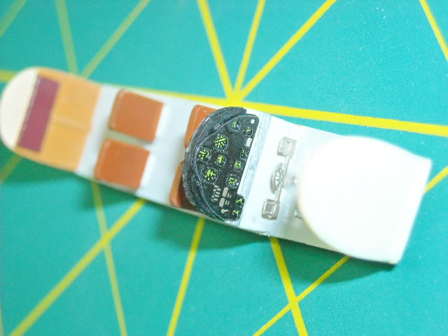
Etched parts, throttle and handles for the cockpit sides were carefully cut from the fret, bent and installed with CA glue as well as the rudder pedals on the floor and the instrument panel, very nicely pre-painted, on the front cockpit bulkhead. The painted the control stick and the finished seats were set aside to be installed later, as I wanted to use tissue paper to blank the cockpit area for spraying. I masked the passenger windows on the starboard fuselage from the inside with small strips of Tamiya masking tape. The passenger and cockpit sections were fastened to the starboard fuselage with CA glue and the fuselage closed. The head rest fairing, after some sanding and test-fitting was added and CA glue was used to fill the fuselage seam.
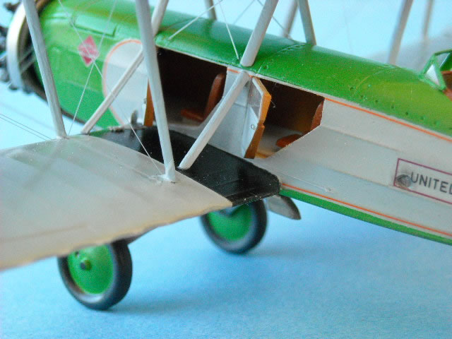
As I wanted to show the two doors to the passenger compartment open I stuffed wet tissue pager in the opening for the later spraying sessions. The clear cast resin doors had the window sections masked from both sides and a 10. thou plastic card was used to thicken the door below the windows to give it the look of the doors as seen on the colour photos seen on the recently restored Boeing 40B-4 found on the internet. The inside of the door was painted Humbrol # 62 Light Brown and the outside would be sprayed with the fuselage sides and wings “French Grey”.
The fuselage seams were rubbed down with just a couple of sections being retreated. The headrest fairing was another matter. Two more fillings with CA glue and than two applications of Mr. Surfacer 500 were necessary to blend it smoothly with the fuselage. I drilled holes in the rudder (2 x above and below the elevator) and elevators for operating arms and installed the vertical tail surface. Filled the mating surface on both sides with CA glue and rubbed it down after an hour. Before the horizontal tail surfaces were added, I drilled all the holes for the rudder (4x) and elevator (2x each side) control wires in the rear fuselage. The seams were filled and rubbed down and the struts installed underneath the horizontal tail surfaces. Next the tail skid and housing was added and when set the skid part was cut off, a hole drilled into the housing and a short section of slightly bent brass wire was glued in place.
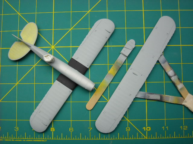
The fuselage, upper and lower wings as well as the wheels where primed with Tamiya grey primer. After 24 hours of drying, they were lightly sanded and some areas re-primed. While this dried I mixed the “French Grey”, “Boeing Green” and International Orange.
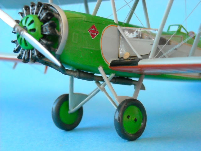
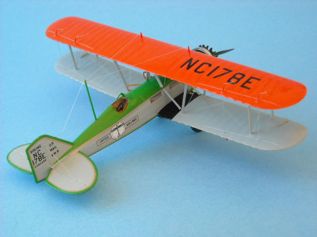
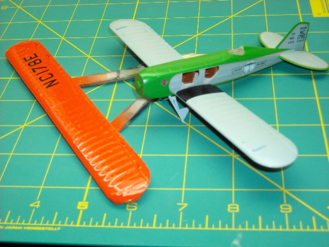
The “French Grey” was mixed from Model Master Light Gray FS 36 495 to which I added a few drops of Humbrol Gloss # 101 Green. For the “Boeing Green“ Humbrol Gloss # 101 Green was lightened with Satin # 130 White. When making a test colour card of the of the Model Master International Orange, I found it too red and dark in comparison to the colour pictures I got from Bill Coffman showing Boeing 40B-4 in the Henry Ford Museum and the Chicago Museum. I added Model Master Bright Yellow to the Model Master International Orange until it was lighter and more orange coloured.
Having read the Boeing 40B-4 write-up in Scale Aviation Modeller International, Vol. 15, Issue 1, January 2009, I filled the rear out-side locating hole on the lower wing for the strut and drilled a new one 1.5 mm forward of the original location. On the fuselage and on the wings holes were drilled with a number 80 drill for the rigging wires (double wires on the wings. Also drilled were holes for the aileron control wires above and below the wings. The lower wings were installed and wooden stir sticks were put under the wing tips to ensure the 2° dihedral. After the CA glue had cured, the seams were filled and sanded.
The “French Grey” was sprayed on the fuselage sides and all tail surfaces and to the lower part of the upper wing and the upper part of the lower wing.
After drying for 24 hours it was time to apply the supplied masks for horizontal and vertical tail surfaces. Before I glued these parts to the fuselage I had placed these parts onto the decal sheet to confirm the later placement of the thin orange-red strips. I knew that I would have to modify the masks to make things later fit better and that I also had to trim and or cut the decals to make them fit. To make the masks fit, I scanned the decal sheet and cut the tail surfaces out on the orange-red line, trimmed them to fit the tail surfaces correctly and used the cut-outs to trim the masks accordingly. On the masks for the vertical tail I cut 1 mm. of the rear and on the horizontal surfaces a sliver was trimmed from the rear section and about 2 mm. were it fitted to the vertical tail.
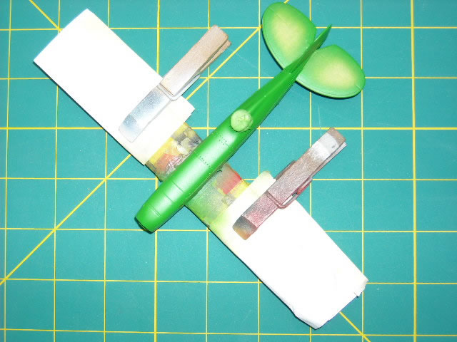
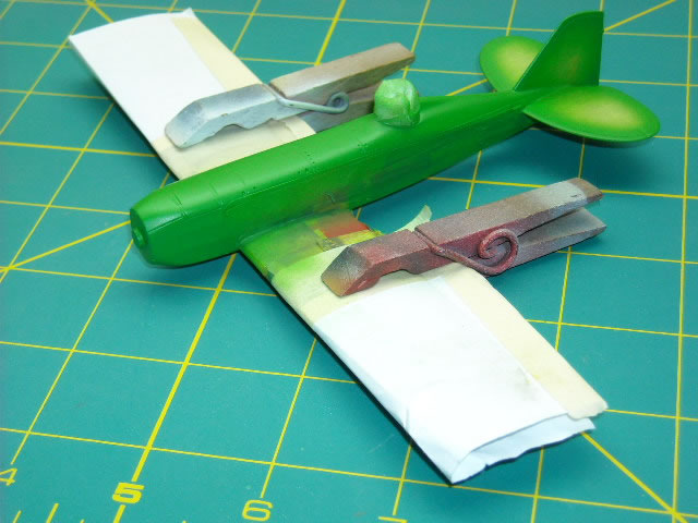
The fuselage mask was not supplied but was easily made with a circle cut from Tamiya tape and cut in half and placed just in front of the leading edge of the lower wing. The dimensions for the circle came from measuring the fuselage and it was a little smaller than the decal sheet dimensions. The rest was covered with strips of Tamiya tape, using pictures and the colour instruction sheet as a guide. After the lower wing was masked with paper and tape the “Boeing Green” was sprayed onto the fuselage, the edge of the tail surfaces, the cowl cover and wheels.
Left to dry for two days, the masks from the lower wings were removed and the grey areas of the lower and upper wings masked as well as the bottom of the fuselage to spray the orange-red colour. To do that correctly I installed the landing gear struts so that the model could rest on them while the underside of the lower wing could dry. Before the colour was applied the photo etched control horns were folded and added to the ailerons and the grey areas masked. After spraying the orange-red the model was left again two days to dry.
Finishing Touches
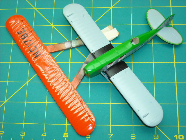
So that I did not break the control horns off while handling the model to install the struts and applying the rigging I cut foam board to fit the wings with cut-out for the control horns. I can say now that it worked very well.
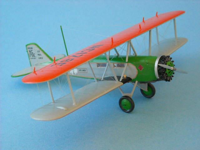
The last items to be sprayed were the black wing walking areas.
The decals made by “Stanislav Mach” are excellent and settled down nicely with only small amounts of setting lotions. I started applying the decals on the lower horizontal tail surfaces first. The decal for the thin orange outline were cut lengthwise and slightly overlapped at the wing tips. No change of colouring was noticed on the small over-laid orange colour sections of the decal. I was pleased and tackled the upper horizontal surfaces next. On the vertical tail decal I cut 1.5 mm. off the back, just behind the lettering, installed the front parts on both sides using plenty of water to slide them into place. After they had dried, the small back sections were added.
The large fuselage decal was installed in sections. The rounded front section was cut off (6 mm.) and the clear decal part on the inside was trimmed very closely to the orange line. This allowed me to curve it inside the green outline and leaving an even grey line between the orange line and the green fuselage paint. The rest of the fuselage decals were added in sections and the registration on the upper and lower wings. All the decals were sprayed with Floquil Crystal Cote mixed with a few drops of Floquil Flat Finish to seal them in.
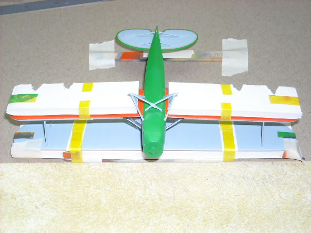
It was time to install the struts. First to be installed were the short lower wing to fuselage struts. Also the doors were installed at this time as it would be difficult to add them when the upper wing was on and the windows on the starboard fuselage were filled with Humbrol Clearfix. To install the upper wing I glued the two outer struts onto the lower wing, carefully checking that they were parallel and measuring that the distance between the left and right set of struts matched the locating holes on the upper wing. An hour later I added the upper wing and left the CA glue to cure overnight.

Next the cabane struts were installed. I did this while kneeing in front of the workbench, this is also a good position to say a little prayer, while installing these small and fiddly parts! To add the angled inboard struts I filled a slight angle at the ends and drilled holes into the ends. Small pieces of sprue were glued into the holes and trimmed to about .5 mm. This made it easier to locate the struts and keeps them in place while the CA cured. With all the struts in place the upper wing to fuselage and lower wing structure felt very solid and with the foam board in place it was very easy to handle the model while installing the rigging.
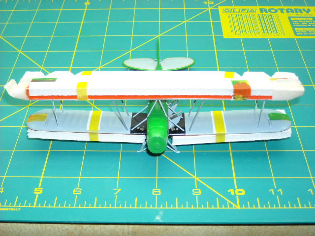
I rig with stretched sprue and it was a full evening’s work to complete it. I started with the rigging the near the cabane struts, then the angled struts and finally the outer struts.
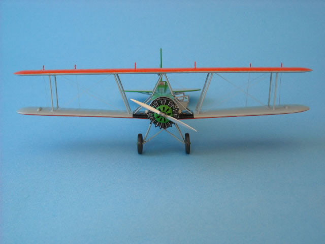
Next came the double flying wires, four on each wing from the lower wing near the fuselage to the upper wing outboard struts. These were tightened with a lit incense stick.
Make sure you keep the heated part moving lengthwise or you start rigging again! The support wires were installed next and this is always fun double wired planes because one of the wires has to be installed between the flying wires. But I got it done too and damaged only one of the flying wires.
The control wires for the rudder and the elevators were added, as well as the tail support wires.
The foam board was removed, the aileron control wires were installed on upper and lower wings and the aileron interconnecting wires.
I added the seat, control stick, windscreen and the wheels. I had earlier drilled the holes for the aerial mast in the fuselage and aerial wire in the leading edge of the upper part of the vertical tail. I used .81 mm brass wire for the aerial mast and installed the pre-painted mast with CA glue. The two short aerial masts were added to the upper wing and painted International Orange. When dry the aerial wires, again using stretched sprue were installed and tightened.
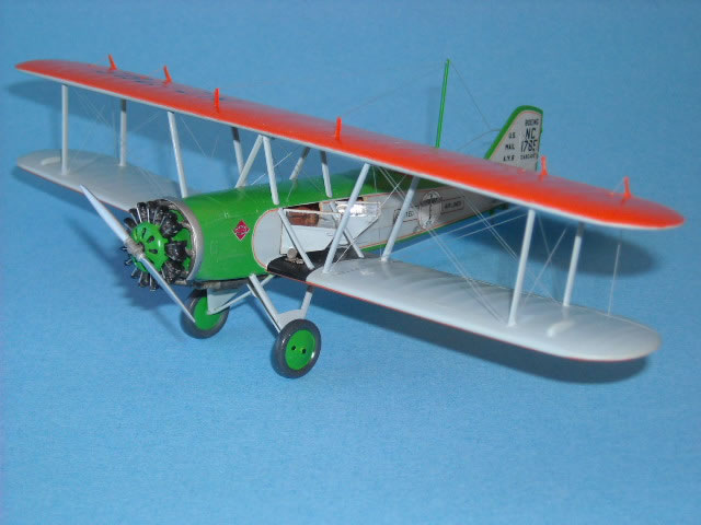
The engine with pushrod made from silver stretched sprue had the cowl cover glued with a few tiny drops of CA. The collector ring was added and the engine installed. After the glue had cured the tailpipe was installed and when this had set the contacts touched up with exhaust paint. The edged pitot tube was folded and installed on the starboard front strut and filler caps and what looks like an instrument were folded and fitted to the inboard wing near the leading edge. Finally the finished propeller, was added and the model was completed.
I found the model an interesting and enjoyable build, with very few problems. The finishing was an exacting task, and not for the faint of heart! This manufacturer continues to issue kits of great interest, and I look forward with interest to further releases.
Reference:
-
Air Enthusiast, Number Twenty-two, 1983,
-
Fine Scale Modeler, October 1986,
-
Scale Aviation Modeller International, Vol. 15, Issue 1, January 2009,
-
Pictures from Bill Coffman and from the Internet.
Model, Images and Text Copyright © 2009 by Bernie Hengst
Page Created 26 May, 2009
Last Updated
26 May, 2009
Back to
HyperScale Main Page

|
 Home
| What's New | Features | Gallery | Reviews | Reference | Resource Guides | Forum |
Home
| What's New | Features | Gallery | Reviews | Reference | Resource Guides | Forum |