|
Mach 2's 1/72
scale
RB-45C Tornado
by Rolf Blattner
|
 |
|
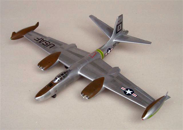
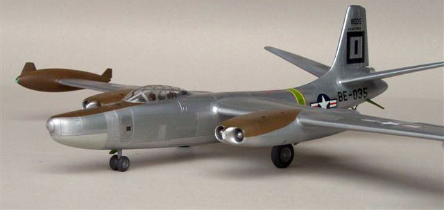
North American RB-45C Tornado
|

Mach 2's
1/72 scale B/RB-45 Tornado is available online from Squadron
The B-45 - first jet bomber of the USAF, the aircraft allowing the
fledgling SAC to develop it’s competence and the last aircraft stemming
from a development competition numbering three types.
An interesting subject in its own but for me irresistible in its
strategic reconnaissance version.
Really something off the beaten track and accordingly also providing
some obstacles.
If you would like to add the model to your collection here is what you
may experience.
Judging from other modellers‘ remarks there seems to be a love-hate
relationship with kits from
Mach 2 - unusual subjects, mostly not available from other
manufacturers, not always easy to build...
Could it be Mr Palix has chosen his trade name with a link to German?
Reading in German the manufacturers name "Mach 2" sounds exactly like
"make 2".
To be honest, I almost had to do that.
Be warned – this is not the contemporary "Tamigawa"
kit.
To start with – the instruction sheet is an A4 copy
with 4 rudimentary drawings, box top and bottom yielding some colour
information. Adequate for brave old hands I suppose.
The grey plastic used is thick and soft, the recessed panel lines not
everywhere well defined and there are many sink marks.
Separating the parts from the thick gates needs care. A dry fit already
showed some deficiencies.
Fuselage, wings, tail, wing tip tanks, everything was just a wee bit
askew or not round. Juggling the parts did not help much.
Cockpit and Fuselage
The cockpit "tub" is wrong, missing a "galley" or
"passageway" from entrance door on the left up into the cockpit.
The necessary modification is not very noticeable after the canopy is
fitted but I found it worth altering.
I cut the left side of the "tub" provided away and fitted part of the
left over console detail below the rim of the cockpit to the left hand
fuselage side. The bulkhead between cockpit and navigator compartment
was altered by cutting and opening the access to the "galley".
The front part of the fuselage seems to "turn left" just a little bit at
the rear of the navigator’s compartment and the cockpit opening is
asymmetrical and slants slightly to the right.
The diameter/geometry of the fuselage halves
differed on my sample. This is especially noticeable in the area of the
cockpit. You might want to try to correct as much as possible at the dry
run stage. Otherwise you will have problems later when you try to adapt
and fit the cockpit - as happened to me.
All these faults are beyond complete remedy after gluing everything
together and fitting of interior detail.
I fitted the cockpit tub in the right fuselage, added the necessary
support between cockpit floor and nose wheel bay, fitting and adding the
bulkhead of the navigator compartment before joining the fuselage halves
and the forward upper nose decking (glazing for the bomber version).
Be warned – that’s the point where you have to find room for at least 25
grams of ballast in the extreme nose ! With that big tail and a lot of
thick plastik at the rear you will have a tail sitter with anything
less. If you are doing the bomber version with the glazed nose you will
have to pack as much as possible into the lower part of the nose (radome)
and believe me, more than 30 grams will be taxing for the undercarriage
struts as the model is already heavy enough on its own.
Ask your friendly tire dealer if you can have flat
balancing weights for aluminum wheels and adapt it to the form of the
radome bay or use fine lead shot.
Wings
Only after gluing the wings together I realised a
marked dip or kink in the upper wing surface outboard of the engine
pods, resulting in a noticeable upward bend of the trailing edge and a
"hollow" look of the top surface.
The bend was (partly) overcome by manufacturing new ailerons and
adapting the remaining trailing edge of flaps and wing with plastic
putty and paring to a realistic look. No real remedy for the "hollow"
look however if you do not want to apply a lot of putty with consequent
loss of the existing panel lines and the possible need to modify the
rear upper part of the engine nacelles.
Actually the top surface of the wing is not according to plan and does
not have a "straight" line from root to tip. I suppose this could be at
least partly corrected by fitting a "spar" and forcing wing nose and
trailing edge together when gluing.
The fault is not obvious at first glance when looking at the finished
model but stands out when looking over the wings from head on.
That was the first time when I pondered the decision to "make 2" (i.e. a
second one) or to try to live with the faults ! As getting the kit had
already been time consuming enough I kept going.
Clear Parts
All clear parts are very thick and result in a
distorted look. The navigators overhead window also did not fit and was
undersize. I therefore discarded it and used a piece of clear plastic
from a CD-case as replacement. The variety used was clear styrene and
could be worked, glued, filed and polished like normal plastic.
The canopy is too broad judging from plan and pictures. It was sanded,
adapted to the fuselage contours and used as a master to form a new one.
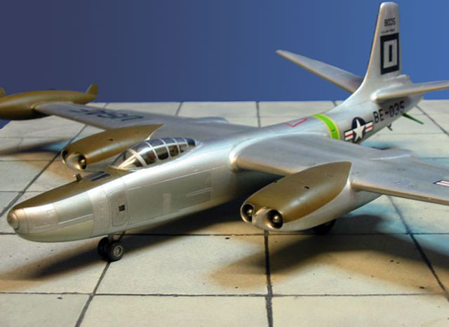
Engine Nacelles
Engine intakes and exhausts are not very detailed
and convincing. I used Evergreen plastic tubing for both and made new
intake cones from rod, using small lock washers for the first compressor
stage.
I was possibly too intent on improving the intakes and did not realise
until too late that the intake lips are angled – the lower lip being set
back. Second "Mach 2" effect !
The engine pods do not have a positive location. A second time around I
would first join fuselage and wings to allow checking proper alignment
of the pods with the fuselage data line viewed in plan AND
with the undercarriage bays. Everything looked fine from above but the
location of the u/c struts relative to the pods now differs on my
example – "Mach 2" effect number three.
Fuselage, Wings and Empennage
At that stage I was more concerned with mating the
wings properly and at right angles to the fuselage. Sounds easy enough
but resulted in a lot of filing and filling of the joints on wings and
fuselage until the left wing was no longer overtaking the right one.
I never trust butt joints, so I used tubing,
telescoping 3 diameters to get a strong spar and support the wings
beyond the undercarriage bays.
The same procedure was used for the horizontal tail where I used tubes
again, suitably heated and bent to the correct dihedral in the middle
and fitted to the fuselage first.
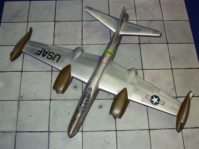
As I wanted a recce version with visible camera ports I cut openings in
the lower rear fuselage for the 3 panoramic cameras, the rear oblique
camera and cut out the bay for the 4 multiple split vertical cameras as
per sketches from the book "spy flights of the cold war" by P.Lashmar.
Camera windows were inserted using clear plastic from the CD case again.
The cameras behind were simulated with tubing, painted matt black and
filled with Krystal Kleer for lenses. Before inserting the camera bay I
stuffed the fuselage with foam rubber fore and aft to avoid any "see
through" effect and possibility of dust or particles getting on the
camera windows from inside.
After puttying, sanding and polishing the windows were masked with tape.
The whole operation was of course handled before mating the fuselage /
wings & tail surfaces.
The completed model was sanded and rescribed where
necessary.
After a definitive coat of suitably thinned Gunze Surfacer 1000 I
airbrushed Humbrol Silver # 11 overall, followed by an overall sealing
with Future. After thorough drying I shaded single panels with 5
different silvers, using 3M post-it notes and 3M post-it tape for
masking.
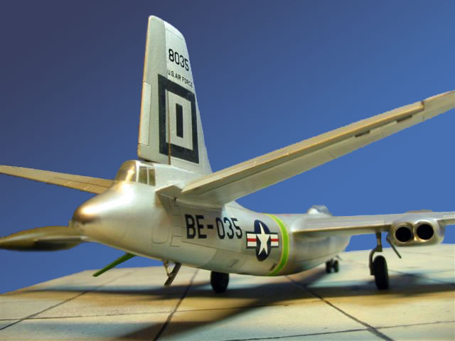
After sealing again with Future the decals were applied. The kit decals
are not to nowadays standard and better left alone. Fortunately I had
the right size USAF and Star&Bar left over from an Italeri Canberra. The
buzz number was made up from single characters from an old "Stoppel"
decal sheet, bought more than 25 years ago and no longer available
unfortunately. The characters are printed directly onto the adhesive –
without any carrier film, difficult to apply but ideal for "silver
birds". Plain decal sheet airbrushed black and yellow-green was cut and
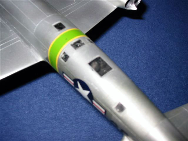
applied for the tail marking and the arrows on the tip tanks. The
fuselage band was masked and airbrushed green, the yellow outlines added
with narrow strips of yellow made from plain decal. After a final coat
of semi gloss acrylic the rest was downhill – no need to explain the
finishing work I suppose.
The kit was difficult to get, expensive and time
consuming to build. Maybe my example was just a bad shot. Nevertheless,
it gave me many more hours of modelling pleasure compared to a
contemporary "shake and bake" kit. And you would never believe how many
younger modellers have already asked "what kind of plane is THIS".
I am still wondering however, if I should have a go at a second one to
apply all lessons learned.
Aviation News Scale plan by Mike Keep / Air
International 1988 / IPMS USA Quarterly ??, details & markings by G.
Knox Bishop / Wings Magazine ?? – "The last great Bomber Fly Off" by Joe
Mizrahi /
Aeroplane Monthly 10/1994 / Alan Sutton, "Spy Flights of the Cold War"
by P. Lashmar, 1996
2 colour pictures from
http://www.photovault.com .
With many thanks to John Sheehan, Terence Marriot, Th. Messmer & P.
Leuenberger for copies and data provided.
Click the thumbnails below to view larger images:
Model, Images and Text Copyright © 2005
by Rolf Blattner
Page Created 15 August, 2005
Last Updated
04 June, 2007
Back to
HyperScale Main Page
|