|
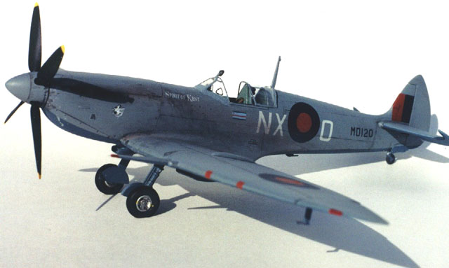
Spitfire HF MK VIIc
by Bob Swaddling
 |
|
Spitfire HF MK VIIc |

ICM's 1/48 scale Spitfire VIIc is available online from Squadron.com
The ICM MK VII Spitfire kit marks the first time that this version of the
Spitfire has been offered in 1/48th scale. After building the ICM MK IX kits and
seeing the poor Quality Control and problems with molding that many modelers
experienced the MK VII kit was a huge improvement. The only sink marks were
ahead of the ailerons on the upper wings. Even the wheels were well molded and
sharp although they are poor representation of real Spitfire wheels and should
be replaced.
Please note that every part of this kit must have mold parting lines
and/or flash removed and then it must be carefully test fitted before it is
finally glued into place. Many have complained about this part of building the
ICM Spitfire series but I find it intriguing and enjoy the concentration on each
part. It reminds me very much of working on the real Spitfire.
Although a very nice Spitfire model can be built straight from the box using
this kit, it is actually only a nice starting point for a scale model MK VII
Spitfire. The extra work that is needed is not difficult and is noticeable to
Spitfire Boffins. I find it fun and a learning experience to do the extra work
and research that results in a true MK VII Spitfire.
I have quite a library of Spitfire books and information, but the best
reference that I have found for the MK VII was an old “Koku-Fan” Japanese
magazine from November 1978 and the 1990 Ian Allan book “Spitfire At War 3” by
Dr. Alfred Price. The Koku-Fan article has many close-up colour cockpit shots of
the world’s only remaining Spitfire MK VII, S/N EN474, an early version of the
MK VII that saw extensive testing in the USA during WWII, and now is on display
at the Smithsonian in Washington D.C. The “Spitfire At War 3” book has an entire
chapter, which deals with 131 Sq. RAF and has many photos of the later MK VII
aircraft from the time period (just before D-Day) that the kit is built to
depict, and one close-up photo of MD120 “Spirit Of Kent”, that removes all doubt
as to where the nose art should be placed.
Building the Fuselage
Since the engine doesn’t fit under the cowling very well and the detail is
very basic in any case, the only part that I used from the engine parts was
“A-21”, the forward half of the propeller reduction gear. Some modelers build up
the engine block only enough to have a mount to glue the exhaust stacks to later
but I don’t bother with this and simply glue styrene backing to the inside of
the side cowls at the exhaust stack openings to support the exhaust stacks much
later in the finishing stages of assembly. I skipped steps 1 and 2. Step 3 shows
you the option of building the kit with the cockpit access door in the “open”
position. Since the HF MK VII had a pressurized cockpit, it was never fitted
with a cockpit access door. In fact I filled the panel lines for the door with
CA glue and sanded the area smooth. Since the only opening to the cockpit would
be the canopy in the slid back position, I opted to not over-do the interior
details, as they would not be seen easily. The interior was painted Testor’s
Model Master RAF Interior Green. Steps 4 and 5 (interior side walls) were done
as per the kit instructions.
Step 6 is where the modifications I made for the MK VII version mostly got
done. First thing was to fabricate a bulkhead that replaces part “B-8” behind
the cockpit area. This was the pressure bulkhead seen on all pressurized cockpit
Spitfires. I traced the outline on to a piece of paper then transferred the
shape to a piece of cardstock. I kept experimenting with the shape till the
cardstock bulkhead fit and then used it to fashion one from sheet styrene. Frame
5, or firewall, (Part “B-23” seen in step 2) was filed down to fit properly
within the fuselage halves without springing them out of shape. As mentioned
earlier, I filled the panel lines for the pilot access door with CA glue and
sanded them smooth. I drilled the mounting holes in the starboard cowl for the
compressor air intake, but didn’t install it at this time. The gear drive bulge
(often confused as used with a Coffman starter as used on the MK II), forward of
the compressor intake on the cowl, remains in place on the MK VII. I also
scribed in a small square panel to represent the cockpit depressurization panel
just below the starboard canopy rail. On both fuselage halves I cut the area for
the small Perspex panel, behind the sliding portion of the canopy, down to the
same level as the rest of the cockpit area. I also cut away the areas for the
retractable tail wheel. The external canopy runners were installed and care
should be taken here that they are of the correct length. They only extend back
as far as the rear of the Perspex area. I used Evergreen strip styrene to
replicate the external runners.
The elevators were cut away from the horizontal stabilizers at this time. I
left the horizontal stabilizers off till after painting. Both fuselage half
joining areas were sanded smooth and glued together. The seams were cleaned up
and no filler was required.
The cockpit interior assembly in step 7 and 8 was done, as per kit
instructions except for the removal of the pilot’s headrest and the substitution
of the Ultracast seat with Sutton harness. I cut masking tape extensions for the
harness to extend through the opened passage through the pilot’s head armour
plate as per the real aircraft. I left the gun sight off till later when
installing the windscreen.
In Step 9 the cockpit interior is installed into the fuselage halves. I find
that the interior parts need some filing and trial fitting till they fit
properly. They must not exert pressure on the fuselage sides, as this will
affect the dihedral of the wing later.
ICM instructs you to use the wrong tail wheel from the kit. This is the
non-retractable tail wheel and the retractable tail wheel of the real aircraft
is very different. ICM does not supply the proper part. The Hasegawa MK IX kit
gives you a beautiful retractable tail wheel as an extra, unused part, so I
modified it to use on the ICM kit. I didn’t install it till later in the
assembly.
Building the Wings
The next step is where I jump ahead to the wing assembly. The wing assembly is
part of the equation for the final fit for the cowls and so must be together for
trial fitting. ICM flashes over all the shell ejector chutes on the underside of
the wing. This is much better for the modeler in that it is easier to open the
ejector chutes you need for the wing armament that you are depicting, than it is
to fill in the unused chutes as on the Hasegawa kit. The Spitfire MK VII used
the “c” wing armament with four .303 M/G’s and two 20mm Hispano Cannon. First I
opened the .303 shell ejector chutes on the wing underside. Be careful here as
they are molded backwards and the wider part of the “L” shape should be oriented
toward the leading edge, not the trailing edge, as ICM has done them. This is an
easy fix with a small file and some care.
At this time I laid out and scribed in the leading edge fuel tanks. I used
the 1/48th scale drawings from the SAM Publications book “The Supermarine
Spitfire (Part 1: Merlin Powered) Modellers Datafile – 3” for reference for the
dimensions. The cannon bay interiors have the option of being displayed in the
open position and ICM gives you some cannon breeches and ammunition feeds for
display, but there is much more detail needed in these to meet my standards so I
glue mine in the closed position. I opted to use the much more accurate
Ultracast “c” wing cannon bay covers since the ICM covers are not defined
enough. I used CA glue to mount these in place. These covers do make a huge
difference in final appearance and are worth the extra cost. Ultracast also has
the double cannon covers and the “e” wing covers, all much improved over the ICM
kit parts.
The wing upper and lower mating surfaces were sanded smooth and extra sanding
was required near the joint for the wingtips to get this area to be the same
thickness as the wingtips. Then the upper wings were carefully glued to the
bottom section.
Next I fit the wing assembly to the fuselage. Since this was my fourth ICM
Spitfire kit I knew that the rearmost part of the lower wing, which butts up to
the lower fuselage, needs to be filed much shorter to allow the wing assembly to
move rearward till the leading edge wing root upper and lower halves line up.
When this happens the whole upper wing joint lines up with the “V” shape at the
root mating perfectly. I taped this in position and turned my attention back to
the fuselage and the cowls. The MK VII Spitfire used the early style carburetor
air intake and this is pointed out in the kit instructions. However, the kit
parts are undersize and resemble the air intake of the MK V. The MK VII and
early MK IX air intake was much larger and had it’s own distinct shape.
Ultracast supplies this part that is much improved over the kit part. It is made
to fit the ICM kit and does so with no difficulty. The upper cowl has the bulge
over the intercooler and needs to be test fitted and filed/sanded to proper fit.
The only part used from the forward engine/cowl assembly in step 6 is part
“B-25”. I file and sand it down till it is just big enough to hold all four cowl
pieces at the front while allowing them to all touch properly. I glued the part
“A-21” to rear of this to have a propeller shaft in the proper place. I then
glued all the cowl pieces together, using CA on the Ultracast resin part and
making sure that they all fit around part “B-25” properly. Now is the time to
glue the wing assembly to the fuselage. The dihedral will be set with this so
care must be taken to get the upper wing roots solid together. Later I filled
the rear part of the underside wing part to the fuselage joint with CA glue.
This was the only filler used on the entire kit other than the aileron sink
marks. After cleaning up the seams I drilled out the cine camera opening on the
starboard wing root and the much larger fuel cooler inlet on the port wing root.
The wingtips were installed next, still watching for proper continuation of
the dihedral. The ailerons were shortened accordingly and installed next. This
completes the basic structure to which everything that goes on from this point
on is a subassembly. I worked on subassemblies all through the main structure
assemblies while waiting for glue to dry.
The radiator interiors and the areas on the lower wing where they would be
installed were painted the underside colour, Testor’s Model Master PRU Blue. The
radiator cores were painted and fitted and the radiators installed. The air
intake for the compressor was installed on the starboard cowl at this time.
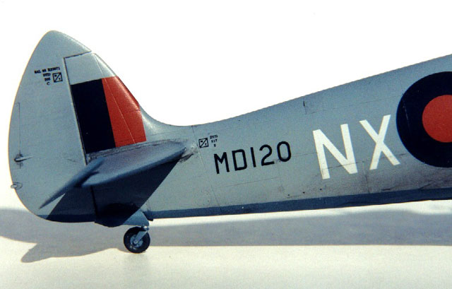
MD120 and all the 131 Squadron MK VII Spitfires, was fitted with the beam
approach “boat antenna”. I drilled the mounting hole on the lower fuselage and
used the “boat antenna” from the Hasegawa MK IX kit.
The horizontal stabilizers were filed at an angle at the hinge line for the
elevators. I used Ultracast late style elevators and fitted them to the
stabilizers to be sure that they would be at the proper angle of “full down”
position when it came time for them to be glued on later. I taped them to a
cardboard panel for painting.
 At this time I masked the cockpit and airbrushed the entire upper portion of
the aircraft, the horizontal stabilizers and elevators, Testor’s Sea Grey Medium
enamel. At this time I masked the cockpit and airbrushed the entire upper portion of
the aircraft, the horizontal stabilizers and elevators, Testor’s Sea Grey Medium
enamel.
When dry, masking was applied, and the underside, including the wheel
wells, was painted PRU Blue. The upper/lower masking was removed and the
horizontal stabilizers were installed and the elevators left to be installed
later.
After the stabilizers were dry and any paint was touched up, I clear
glossed the entire aircraft. I prefer to use Testor’s Acryl Clear Gloss instead
of the ever popular, and overrated, Future Floor Wax.
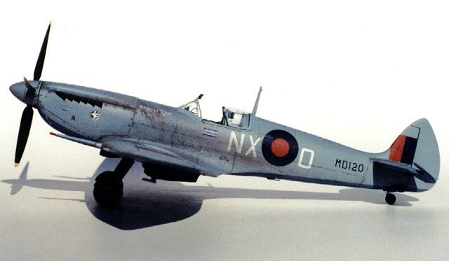
Decals came next using Micro Set and Micro Sol. I used the decals from
Aeromaster sheet 48-210, Spitfires at War Part II that cover the same aircraft
as the kit decals. These markings depict the Spitfire HF MK VIIc S/N MD120 coded
NX-O flown by S/L James O’Meara of 131 Squadron in early June 1944, before D-Day
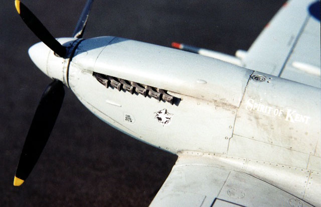
stripes were applied. There is a very nice close-up photo of “Spirit of Kent”
showing the exact location of the nose art on this aircraft on page 76 in
“Spitfire at WAR 3”. This proves that both Aeromaster and ICM instruct the
modeler to place the decals in the same general area but not actually where they
were on the real MD120.
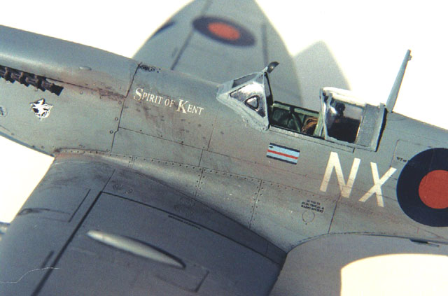
After the decals were applied and had dried I started the weathering process
by darkening the panel lines. With the “plain vanilla” paint scheme used on the
high altitude Spitfire, I thought that it looked rather anemic and needed
something to give it some subtle colour to break the boredom. In the close-up
photos in “Spitfire at War 3”, the weathering shows up with panel lines, light
exhaust stains, and minor paint chipping. For the panel line shading, I used
kid’s watercolours mixed with water and some detergent into a dark gray colour.
After slopping this mixture into panel lines, Dzus fasteners, and inspection
panels, I wiped the excess off with a damp tissue, being careful not to wipe
along the panel lines. After completion of this initial weathering step, I flat
coated the entire aircraft with Testor’s Acryl Clear Flat. All masking was
removed from the cockpit area and the inside of the radiators.
Finishing the Subassemblies
The undercarriage of the ICM kit is a bit too long and makes the nose of the
finished aircraft sit too high. I cut each oleo leg off at the sliding part and
removed approximately half the length of the sliding portion. I then drilled
each part to be reattached an added a small length of brass rod CA’d into place
and glue the other half back together being careful to line up the orientation
of the wheel pintle to the oleo leg. The brass rod gives the part strength. The
oleo torque link scissors were left off, as the MK VII’s did not have them
according to my references. The “up-lock” rings on the oleo legs were drilled
out and thinned down as thin as possible. I painted the oleo legs PRU Blue and
picked out the sliding portion with Chrome Silver. The “up-lock” rings were
painted a dark steel colour. The U/C fairings were painted PRU Blue and glued
into place on the oleo legs. ICM supplies the proper “four spoke” (four indent)
main wheels but although they are well molded now, when compared to the early MK
IX kits, they are not well done and don’t truly resemble a Spitfire wheel. I
used the excellent Ultracast four spoke wheels. I painted the wheel portion
Aluminum and the tyre Floquil Grimy Black. I then painted the portion of the
tyre that is in contact with the ground Flat Black. I also added the yellow
creep marks on the wheels and tyres. The tail wheel strut was painted PRU Blue
along with the inner portion of the wheel and then I drybrushed both with
Aluminum. The tail wheel tyre was painted the same as the main wheel tyres. The
wheels were left off the oleo legs till later and the finished oleos set aside.
I used the Ultracast propeller and spinner. I know that they are the correct
dimensions as I helped Kevin from Ultracast with these measurements from the
spares I have access to. The spinner was drilled to accept the ICM propeller
shaft and painted Medium Sea Gray. The propeller blades were painted and glued
into the spinner making sure that they were all at the same pitch, full course
for engine shut down. The prop was set aside to be installed last.
I used Ultracast exhaust stacks and painted them with Testor’s Metalizer
Exhaust followed by dry brushed Burnt Iron. They were glued on at this time.
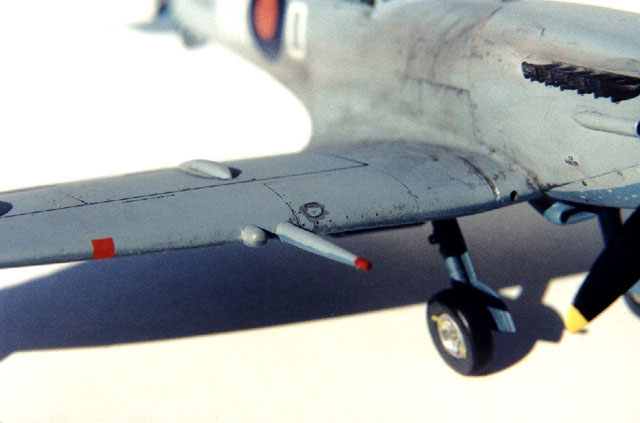
The cannon barrels and hemispherical stub covers were installed and painted.
The tip portion of the cannon barrels was painted dull red to replicate the
rubber protective covers.
I had been planning to use the kit windscreen and sliding canopy and
fabricating the extended rear Perspex from clear acetate. I had my home-made
clear part made and installed when my Falcon Spitfire Special 1/48 scale canopy
set arrived from New Zealand. They include a Lobelle canopy for the MK VII so I
used the parts intended for the ICM kit. I painted the frames Medium Sea Gray
and the inside of the frames Semi Gloss Black. The triangular clear vision panel
in the windscreen was edged in black as the real one had a black rubber gasket.
I notched the rear center of the sliding canopy to clear the radio mast when
slid all the way to the rear, and the windscreen was notched to take the ICM
mirror. The mirror was installed and painted. According to my references, the
round mirror fairing was a dark colour (not black) and I think that it was Dark
Green from the original temperate camouflage paint scheme, so that is what I
painted mine. After painting and installing the gun sight, I removed my scratch
built Perspex and installed the radio mast and clear parts.
The elevators were now glued into place being careful that they are both at
the same full down angle.
Now the oleo legs and tail wheel were glued in place. After they were dry the
wheels were glued on with white glue and adjusted to sit at the correct angle
while sitting on a flat surface. The tail wheel doors were painted and installed
next.
The IFF rod antenna was made from a piece of brass rod and installed in a
hole drilled just forward of the starboard aileron and painted Steel. I also
installed the pitot head and amber signal light at the same time.
I painted the wingtip position lights silver and then followed with acrylic
clear red and green.
Finally I pushed the propeller on the shaft and the assembly was complete.
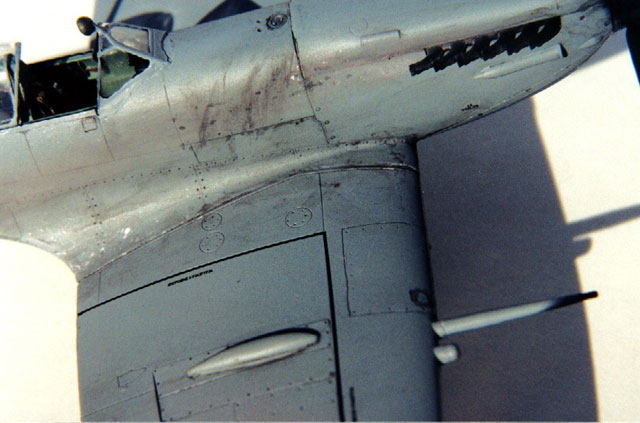
The paint chipping was done using aluminum paint. I kept the chipping minimal
as per my reference photos. I continued my use of kid’s watercolours to weather
the undercarriage and oil stained belly. Then I switched to pastel chalks using
a light gray mixed with black and dark rust colour to come up with the light
exhaust stain seen in my reference photos. I dusted this in the exhaust pattern
and on the exhaust stacks. Next I “washed” some of this down from the fuel fill
area to replicate how fuel spilled during refueling washes the exhaust stain
down the sides of the fuselage. I then put some very small flecks of my oil mix
into the exhaust stain area as seen on the real aircraft. I added some cordite
burns from the shell ejector chutes with black pastel chalk.
This concludes the ICM HF MK VIIc Spitfire.
I very much enjoyed the entire building of this kit. She looks very different
with her high altitude paint scheme and long “pointy” wings when sitting amongst
all the regular camouflaged Spits on my display shelf. On closer inspection you
can see all the features that make this model a true MK VII. She fills in a big
gap in my 1/48th Spitfire collection. Later I would like to build an early
version of the VII with the regular rudder and camouflage like EN474 in the
Smithsonian.
Click the thumbnails below to view
larger images:
Model, Images and
Article Copyright © 2002 by Bob Swaddling
Page Created 08 April 2002
Last updated 04 June 2007
Back to HyperScale Main Page
Back to Features Page |
 Home
| What's New |
Features |
Gallery |
Reviews |
Reference |
Forum |
Search
Home
| What's New |
Features |
Gallery |
Reviews |
Reference |
Forum |
Search

