|
Sud-Est S.E. 100
by
Frank Mitchell
|
|
|
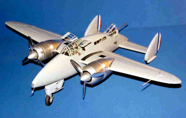
S.E. 100 in 1/32 Scale
(What in 1/32 Scale??) |

HyperScale is proudly supported by
Squadron.com
In the 1930s, planners in many countries thought that the
twin-engine, heavily-armed, multi-place heavy fighter could both defend
against enemy bombers, and escort friendly ones. That concept bred a
number of designs such as the Me-110, the Me-410, the Bell Airacuda, and
others. France produced several such designs, and among the most
interesting was the Sud-Est (or SNCASE) S.E. 100.
This aircraft was to be armed with four 20mm cannon firing forward, and
one cannon in a flexible mount at the rear of the fuselage. The
fuselage, containing three crew members, was comparatively short and
deep which allowed the rear gunner a wide range of fire. The twin
tailfins also contributed to the wide field of fire and also contained
retractable tailwheels. The aircraft had a very large and complex
single-wheel nose gear which carried out all the braking and steering.
The wing structure was plywood, and had flaps taking up most of the
trailing edge, which led to the incorporation of unique, tip-mounted
ailerons.
The first prototype, nicknamed the Limande (lemon sole), was flown
fairly extensively and successfully beginning in mid-1939, but was also
very heavy and underpowered. Although the specified armament was not
installed in this airplane, the rear cannon was mounted for test
purposes, but was not fired in the air (probably a Good Thing). This
prototype crashed due to a runaway propeller in 1940. A second prototype
was under construction, but did not fly due to the outbreak of WWII.
This aircraft has always fascinated me and the occasional photo that
showed up just made me more interested in doing a model. Recently, I was
able to obtain a fair amount of information from France which included a
number of in-construction photos. This gave me the confidence to tackle
the beast.
In brief, everything was scratch-built except for a steering wheel
stolen from a 32nd scale car kit, two O-rings from the hardware store
(rear tires), and two (highly modified) props from a Scratchbuilder’s
Me-410.
The build article is really a picture album; explanations and comments
are keyed to the photos. The model was built in 1/32 scale.
Picture 1 - Balsa Molds
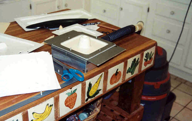
Balsa molds were carved for the wings, horizontal stabilizer, fin,
nacelles, engines, and spinners. These were then vacuum-formed in my
kitchen using home-built equipment that is some thirty years old and
which was the brainchild of the late and great George Lee.
Pictures 2, 3, 4, 5
Building Board & Fuselage
As with all my scratch-built models, the first order of business to
make up a building board. This consisted of a piece of thick ( ¾”)
plywood that was checked for “flatness” and was big enough to contain
most of the aircraft. A vertical hole is drilled to accept a
suitably-sized piece of brass tubing. This is epoxied in place using a
square to assure that it is in fact, vertical. A piece of tubing one
size larger was epoxied to one of the fuselage halves, again making sure
it was vertical and at right angles to the fuselage center line. A
groove was cut in the other fuselage half to accept the tubing. Now,
when the fuselage was assembled or simply taped together, it could be
slipped down over the tubing and was vertically and horizontally
aligned. A pencil line was drawn on the board at the center of the
fuselage and scrap pieces of balsa were CA’d on the base to assure that
whenever mounted, the structure was in the same position. Lots more
balsa pieces were added as construction proceeds to assure correct
placement of wings, tail, engines, etc.
Click the thumbnails below
to view larger images:
[photogallery/photo20180/real.htm]
Picture 5 - Windows
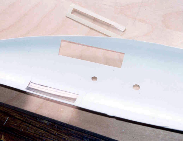
To make the windows, holes were cut in the fuselage sides to accept
pieces of 32nd inch Plexiglas that had been formed over the fuselage
mold. These were made larger than the actual windows to make sure that
the final appearance is as clean as possible.
Picture 6 - Interior Structure
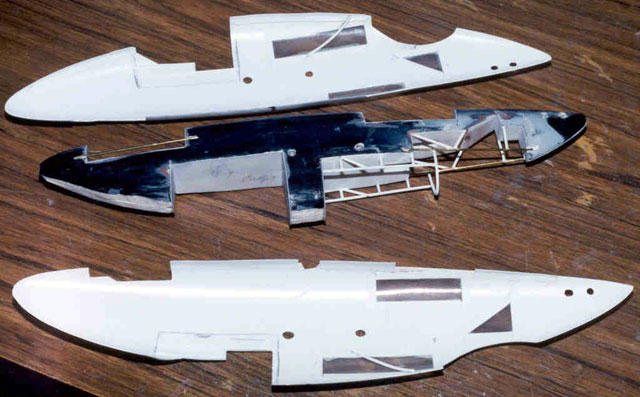
I attempt to leave as much wood as possible inside the plastic to
assure strength and ease of assembly. As the balsa is cut away, the wood
is lined with thin stryrene to allow for detailing and finishing.
Interior structure was added as necessary in those areas that will be
visible on the finished model.
Pictures 7, 8, 9 - Interior
The interior was built in a pretty much standard way, one small piece
at a time (there aren’t many aftermarket sets for this airplane).
Click the thumbnails below
to view larger images:
[photogallery/photo21892/real.htm]
Picture 10 - Joining the Fuselage Halves
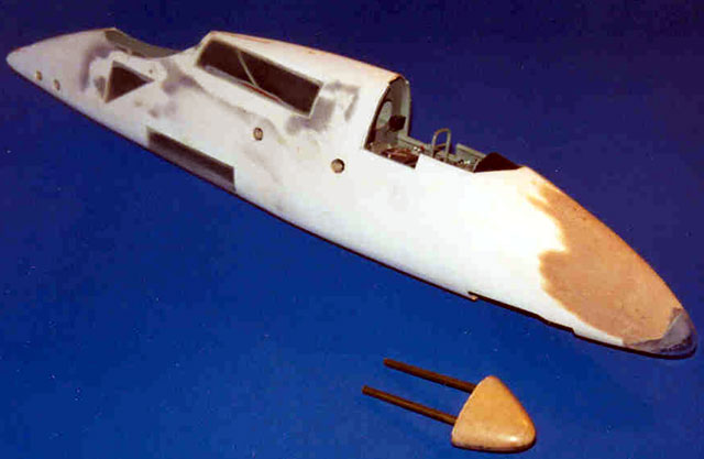
The fuselage halves were permanently joined using epoxy and strips of
thin plastic along the edges. A new mold was made for the nose landing
gear light housing and this was heat-and-smash molded in two halves
using Plexiglas. After a landing light was mounted on the fuselage, the
clear nose was epoxied in place.
Picture 11-12 - Canopy and Doors
The cockpit canopy (and the rear turret canopy) were molded
from1/32nd Plexiglas over the pieces cut from the fuselage molds, thus
assuring a good fit. Entry doors were cut from the same material and
mountings built as appropriate.
Click the thumbnails below
to view larger images:
[photogallery/photo16538/real.htm]
Pictures 13, 14, 15 - Tail and Details
The rear cannon, the rather complex nose gear, and all
the tail pieces were built from a little of everything, but lots of
aluminum and brass tubing were used.
Click the thumbnails below
to view larger images:
[photogallery/photo22233/real.htm]
Picture 16: Stabilizer and Rear
Wheels
The wood mold for the stabilizer was left inside the
plastic to assure a strong bond with the fuselage, but the fins were
made in the usual vacuumed-formed way since (a) they all came from the
same mold, and (b) because the interior had to be hollow to accept the
rear wheels.
The forks for the rear wheels were made from styrene, brass rod and
aluminum tubing. The wheels were turned from acrylic rod, detailed, and
rubber O-rings were used for tires.
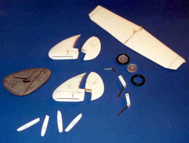
Pictures 17, 18 - Wings and
Control Surfaces
The wings were rather simple on this model. The
vac-formed skins were epoxied to the balsa cores, and holes were drilled
into the roots to accept the brass rods that go through the fuselage to
serve as carry-through structures. The control surfaces were cut from
the wing, cleaned up, and prepared for re-mounting using brass pins. The
were aligned to the fuselage using the building board and scrap balsa
CA’d to the board to assure they would be permanently attached the same
way.
The model was constantly checked for placement and “square” on the
building board.
Click the thumbnails below
to view larger images:
[photogallery/photo10565/real.htm]
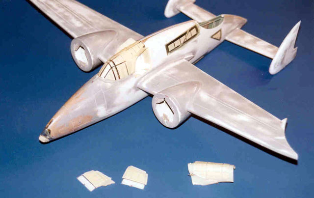
Pictures 19, 20 - Engine Nacelles
The nacelles were vac-formed in two halves then joined
using thin strips of styrene. They were cut to fit the wings and aligned
on the board.
Due to the somewhat odd cowling configuration, the engines were
vac-formed twice for each side. The depth of the leading ring section
was marked on two moldings, and that section removed. The engines
received similar treatment, but the dividing line was slightly longer
due to the rear cowling sloping under the forward ring. Some ¼” balsa
cross-braces were epoxied inside the main engine sections, and these
were pinned and fitted to the nacelles. Scrap ¼” balsa was also glued to
the front of each main engine section and sanded to fit under the
forward ring. Rectangular-section brass was used to form the two small
intakes on each side of the engine and the outer rings notched to match.
Because the spinner fits tightly within the cowling, there are no
engines necessary (Thankfully). The under-cowling intake was formed from
thin styrene and fitted in place.
The spinners were cut from their moldings, and holes drilled to receive
the propeller blades, which were modified from some spare
Scratchbuilders Me-410 props.
Once all this was done, assembly began by simply gluing everything
together on the building board. Epoxy was the primary adhesive.
Click the thumbnails below
to view larger images:
[photogallery/photo27575/real.htm]
Picture 21: Filling and Finishing
There was a fair amount of filling, sanding, puttying,
priming (automotive lacquer primer), scribing, ad nauseam, but when that
was finished, masking was done (3 evenings to do; 30 seconds to spray),
and painting began.
According to two different contemporary accounts, the airplane was gray
with natural metal nacelles, engines, and props. The wheel wells and
gear (I guessed) are French blue-gray. The overall gray is a combination
of several shades of Gunze. The final coating was Floquil Flat Finish
(which isn’t flat, but gives a beautiful semi-gloss that looks good on
32nd aircraft).
The natural metal parts are a combination of Alclad and Scale Metal (a
long-dead, but much lamented Canadian adhesive foil that was [is]
marvelous to work with; Jerry Campbell—are you listening?).
The tail stripes were masked and painted in red, white, and blue and the
data was applied with decals from the stash.
Yes, I know it is weird, but it is undeniably interesting and was a
great modeling project!
Click the thumbnails below to view larger
images:
[photogallery/photo21327/real.htm]
Model, Images and Text Copyright © 2002 by
Frank Mitchell
Page Created 19 November, 2002
Last Updated 04 June, 2007
Back to HyperScale
Main Page
Back to
Features Index
|
 Home
| What's New |
Features |
Gallery |
Reviews |
Reference |
Forum |
Search
Home
| What's New |
Features |
Gallery |
Reviews |
Reference |
Forum |
Search