|
Henschel Hs 129B-0
with SG 113A Förstersonde
by
Ian
Robertson
 |
|
Henschel Hs 129B-0
with SG 113A Förstersonde |

Hasegawa's 1/48
scale Henschel Hs 129B-2 is available online from
Squadron.com
The massive buildup of Russian armored strength throughout WWII prompted the
Luftwaffe to experiment with many radical anti-tank weapons. One such weapon was
the SG (Sondergerät = Special Device) 113A Förstersonde (Ranger Probe)
recoilless anti-tank mortar. The weapon consisted of a 1.6 m smooth bore barrel
capable of firing a 77mm armor piercing shell and its counterweight. The
counterweight was needed to cancel the massive recoil that resulted from firing
the shell.
Experimental arrangements of six-barrelled versions of the SG 113A were fitted
into the fuselage of three Henschel Hs.129s (W.Nr. 0016, 140499, and 0249) in
late 1944 and early 1945. A T-shaped antenna on the aircraft’s nose sensed the
magnetic field of a large metal object - such as a tank - under the low flying
aircraft. This sensor triggered the six armor piercing shells to fire downward
and slightly rearward. At the same time, the steel counterweights fired
vertically and slightly forward to cancel the recoil. Precision flying was
needed to deploy the weapon because the aircraft flew only 2-3 m above its
target.
The Hs.129 was designed specifically as a ground attack aircraft. As such, it
seemed like the perfect platform for the SG 113A Förstersonde; however, there
was no intention to fit the weapon to operational Hs.129s. If successful, the SG
113A was to be used in combat by the Fw.190 (according to Martin Pegg - see
References). However, the SG 113A program was abandoned toward the end of the
war when supplies became scarce. At the time the program was abandoned it was
concluded that the SG 113A system would not have been satisfactory in battle
because of the inconsistency of hitting the target. Moreover, a test pilot noted
that because of the low altitude required to deploy the weapon, the attacking
Hs129 would have been blown to pieces by the tank’s explosion.
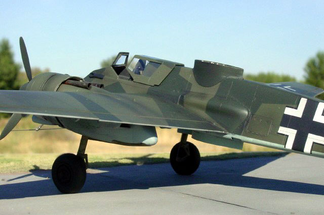
Hs.129B-0, W.Nr. 0016
Hs.129B-0 (W.Nr. 0016) was one of the three Hs129s used for trials of the SG
113A. It had been used previously to test cold starts, tropical filters,
non-standard propellers, FuG 16 radio equipment, cameras, and the Mk 113 cannon.
Two photographs of this aircraft are shown in Pegg (pg 238) and repeated in
Bernád (pg 16).
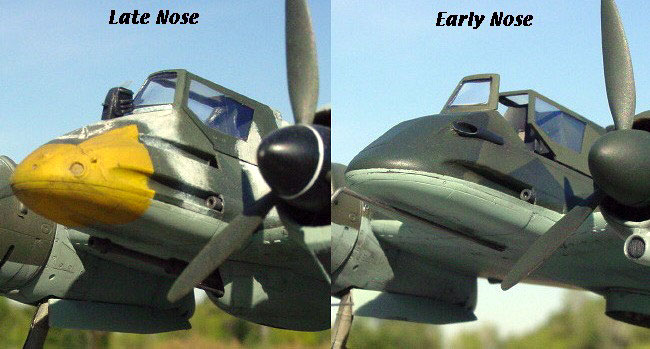
According to Squadron’s “Henschel Hs.129 In Action”, initial Hs.129B-0s were
actually Hs.129A-1s retrofitted with Gnome & Rhone radial engines. Thus, early
B-0s did not conform completely to later Hs.129B-0 standards. This may explain
why W.Nr. 0016 retains the angular nose of the Hs129A (later Hs.129Bs had a
rounded nose) despite having the Gnome & Rhone engine and a canopy typical of
the B series. The aircraft has an enclosed blast tube for the upper gun on each
side of the nose rather than the gun trough typical of later versions. However,
it is not clear from photographs whether the lower gun was also enclosed in a
blast tube. Although some B-0s had the lower blast tube (Bernád 2001), the A
series (and later B variants) had an open gun trough. I opted to retain the open
trough for the lower gun, consistent with an Hs.129A-1.
|
Hasegawa's 1/48 Scale
Hs 129B-1 |
I used Hasegawa’s 1/48 Hs.129B-1 as the basis for my conversion. Hasegawa’s
Hs.129B-2 and B-3 kits would be appropriate for the other two experimental
Hs.129s with SG 113A. However, for W.Nr. 0016 I required an aircraft with the
early cylindrical air intakes beneath the engines.
The Hasegawa kit is a pleasure to build and without major difficulties. I had a
slight but correctable problem with symmetry in the wing dihedral, but this was
due to an error on my part rather than poor fit or design of the kit.
The modifications for the SG 113A apparatus were all scratch built using styrene
(sheets, strips & tubing), aluminum tubing, and wire (see details below). Other
additions to the model included Eduard photo-etched seatbelts, Moskit exhausts,
and brake lines made from electrical wire.
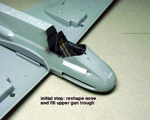
1) Nose Modifications
Once the fuselage halves were cemented together (with cockpit installed) I
was ready to begin the modifications, starting with the nose. The first step in
modifying the nose was to fill in the upper gun trough on each side. I used
cyano-acrylic (CA) glue to attach and fill a piece of Evergreen styrene half-rod
into the trough (see photo). When dry, the piece was filed and sanded flush with
the fuselage.
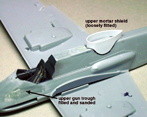
A piece of 0.04 inch styrene tube was used for the upper blast
tube. The blast tube originated at the gun housing above the wing and extended
to about half way between the cockpit and the tip of the nose. For the blast
tube to fit snuggly against the model it was necessary to cut it in half along
most of its length, except near the nose. The opening of the blast tube was cut
at an angle as it appears in photographs. With the blast tube in place, sheet
styrene was faired from the blast tube down to the wing root.
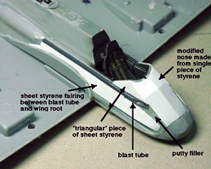 The
rounded profile of the kit’s nose was filed flat, almost to the point of going
through the plastic. Creating the new angular nose was an exercise in origami.
Through trial and error I cut and folded a single piece of sheet styrene to make
the upper nose. With this piece glued in place, small triangular pieces of sheet
styrene were cut to fill the hole between the blast tube, cockpit, and upper
nose on each side of the fuselage. Model Master white putty was used to fill in
the gap in front of the blast tube opening. The
rounded profile of the kit’s nose was filed flat, almost to the point of going
through the plastic. Creating the new angular nose was an exercise in origami.
Through trial and error I cut and folded a single piece of sheet styrene to make
the upper nose. With this piece glued in place, small triangular pieces of sheet
styrene were cut to fill the hole between the blast tube, cockpit, and upper
nose on each side of the fuselage. Model Master white putty was used to fill in
the gap in front of the blast tube opening.
|
|
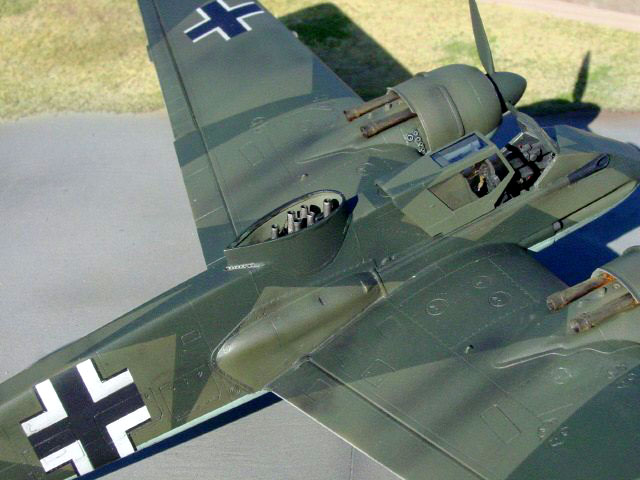
2) Mortar Tubes
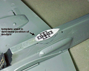 Six
holes were drilled in the upper and lower fuselage to accommodate the SG 113A
mortar tubes. I used schematics from Pegg’s book (pg 243, suitably reduced into
1/48 scale) to determine the proper position of the holes. Note that because the
mortars fired downward and slightly rearward, the exit holes on the underside of
the aircraft should be offset toward the rear of the aircraft. Squadron’s book
indicates the mortar tubes were positioned vertically through the fuselage,
which is incorrect. Six
holes were drilled in the upper and lower fuselage to accommodate the SG 113A
mortar tubes. I used schematics from Pegg’s book (pg 243, suitably reduced into
1/48 scale) to determine the proper position of the holes. Note that because the
mortars fired downward and slightly rearward, the exit holes on the underside of
the aircraft should be offset toward the rear of the aircraft. Squadron’s book
indicates the mortar tubes were positioned vertically through the fuselage,
which is incorrect.
I fashioned a simple housing for the mortar tube assembly using strips of
styrene. Wiring was also added to capture some of the detail shown in Pegg’s
book (pg 238).
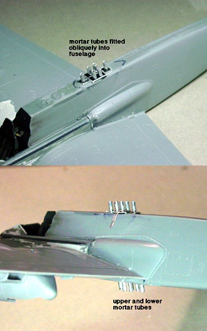 Aluminum
tube was used to simulate the mortars. I used a #11 exacto blade to ream out the
tubes to reduce the thickness of their walls. In retrospect, syringe tubing
would have been better material because it has thinner walls and is more rigid
than the aluminum. The tubes were glued in place at a slight angle (see
explanation above. Also see pg 243 in Pegg). I did not attempt to feed each tube
through the fuselage - getting the pieces to feed into their proper holes would
have been tricky, and symmetrical alignment would have been difficult to
achieve. By using different tubes for the top and bottom parts of each mortar, I
gave myself more room to fiddle with alignment. Aluminum
tube was used to simulate the mortars. I used a #11 exacto blade to ream out the
tubes to reduce the thickness of their walls. In retrospect, syringe tubing
would have been better material because it has thinner walls and is more rigid
than the aluminum. The tubes were glued in place at a slight angle (see
explanation above. Also see pg 243 in Pegg). I did not attempt to feed each tube
through the fuselage - getting the pieces to feed into their proper holes would
have been tricky, and symmetrical alignment would have been difficult to
achieve. By using different tubes for the top and bottom parts of each mortar, I
gave myself more room to fiddle with alignment.
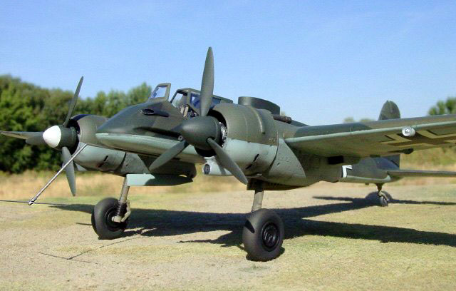
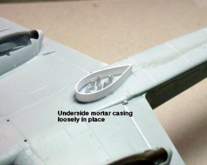
3) Fuselage Casings
Tear-drop shaped (when viewed from above) casings enclosed the mortar tubes
that extended from the upper and lower fuselage. To simulate the lower casing I
cut a strip of sheet styrene and wrapped it into the proper shape (again using
schematics from Pegg on pg 243). The styrene was glued at the narrow end with CA
glue. Once dry, the casing was attached to the underside of the fuselage with CA
glue.
 The upper
casing was more of a challenge to create because it also extends downward over
the fuselage. After figuring out the basic shape I would need, through trial and
error I used a single piece of sheet styrene to produce a casing that fit
snuggly to the fuselage on all sides (refer back to construction image #2). The
casing was glued to the fuselage with CA glue. A thin strip of styrene was glued
along the attachment surface between the casing and the fuselage (see Pegg, pg
241). The upper
casing was more of a challenge to create because it also extends downward over
the fuselage. After figuring out the basic shape I would need, through trial and
error I used a single piece of sheet styrene to produce a casing that fit
snuggly to the fuselage on all sides (refer back to construction image #2). The
casing was glued to the fuselage with CA glue. A thin strip of styrene was glued
along the attachment surface between the casing and the fuselage (see Pegg, pg
241).
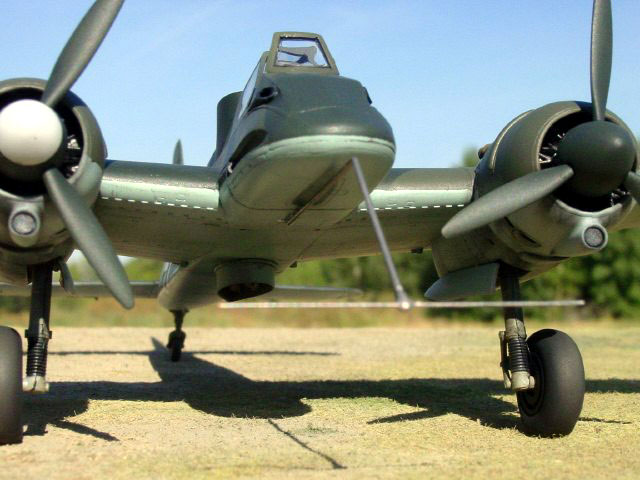
4) Antenna
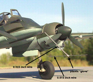 The
T-shaped antenna projecting from the nose was made from three pieces. The main
(thicker) part of the antenna was constructed from 0.025 inch diameter wire bent
into the proper shape (based on photos and schematics from Pegg, pp 238 and
243). The
T-shaped antenna projecting from the nose was made from three pieces. The main
(thicker) part of the antenna was constructed from 0.025 inch diameter wire bent
into the proper shape (based on photos and schematics from Pegg, pp 238 and
243).
The wire was secured to the fuselage by bending the aft tip upward and gluing
it with CA glue into a hole drilled in the underside of the model. I then slid a
small plastic “glove” over the forward tip of the main antenna.
Next I drilled a hole in the glove at a right angle to the main antenna and
horizontal to the ground. I then inserted a piece of 0.015 inch wire to make the
horizontal (“T”) segment of the antenna. The T connection was secured with CA
glue.
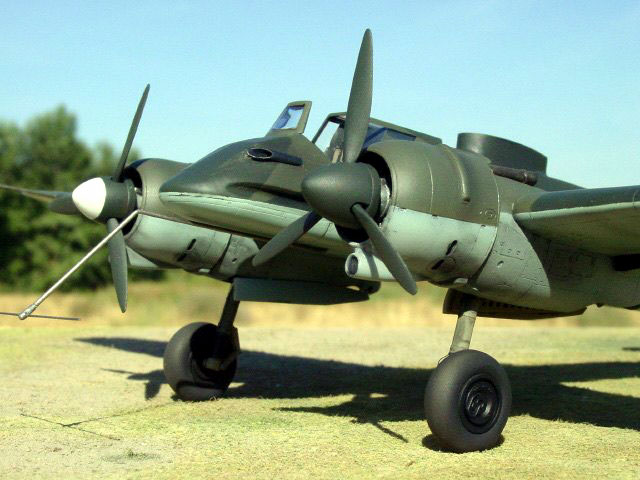
The model was painted with Polly Scale acrylics in standard Luftwaffe colors:
RLM70/71 upper surfaces, RLM65 under surfaces, RLM66 cockpit, RLM02
undercarriage and wheel wells, and RLM70 propeller blades. Based on photographs,
the starboard spinner of W.Nr. 0016 had a light-colored tip - I opted for white.
Exhaust stains were airbrushed using highly thinned black paint. I opted not to
weather the model very much because the aircraft would likely have been well
maintained at the experimental facility.
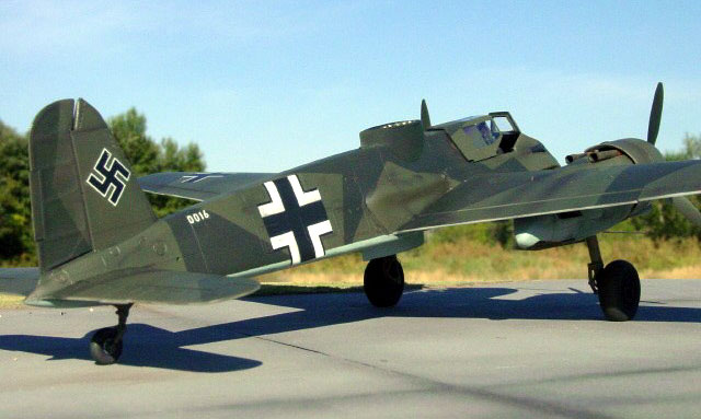
Decals are a mixture of Hasegawa and Aeromaster. The decals for the W.Nr. “0016”
were found in Hasegawa’s Hs.129B-3 kit, although it was necessary to splice them
to get the correct number combination.
All images of the completed model were taken outdoors on a sunny day with a
SONY S-75 digital camera set at its highest picture resolution (2048 x 1536
pixels). Other camera settings were as follows:
-
200 ISO film speed (even though the camera doesn’t
require film!),
-
800-1000th/sec shutter speed,
-
F-stop 8.0 (highest possible), and
-
fixed focus distance of either 20 or 30 cm.
Images were cleaned up using Adobe Photoshop 6.0 for the Macintosh.
Specifically, the interface between the base and background were merged using
the software’s “blur” tool.
Bernád, Dénes. 2001. Henschel Hs 129 In Action. Squadron/Signal Publications
Pegg, Martin. 1997. Hs 129 Panzerjäger! Classic Publications
Click the thumbnails below to view
larger images:
Model, Images and
Article Copyright © 2002 by Ian
Robertson
Page Created 31 October 2002
Last updated 04 June 2007
Back to HyperScale Main Page
Back to Features Page |
 Home
| What's New |
Features |
Gallery |
Reviews |
Reference |
Forum |
Search
Home
| What's New |
Features |
Gallery |
Reviews |
Reference |
Forum |
Search