|
Focke-Wulf Fw
189A
by Matt Swan
|
|
|
Focke-Wulf Fw 189A |

MPM's 1/48 scale Fw 189A
is available online from Squadron.com
The Focke-Wulf Fw 189A
observation plane was a fine example of an aircraft fulfilling its role.
It was so effective that the Allies referred to it as the "Flying Eye".
The craft began its life in the late 1930's in competition with several
other aircraft for an RLM contract to develop a forward observation
platform. One noteworthy competitor was the Blohm und Voss BV-141, which
was arguably the ugliest aircraft of the period. Over 8,000 189's were
produced in three variants; the "A" or observation version, the "B" or
training version and a limited number of "C" ground attack versions.
Today, only one example survives and is currently being restored at the
British Aerospace Museum.
The 189A was powered by a pair of Argus As 410 A-1 inverted V-12 engines
producing 465 horsepower each giving it a top speed of 159 miles per
hour at 22,000 feet. A crew of three manned it; pilot,
observer/bombardier and gunner. Armament was light with two 7mm MG15
machine guns mounted in the gondola and two MG131 13mm cannons mounted
in the wing roots. It could carry a small bomb load and was effective
where air superiority was maintained. The aircraft had the ability to
use short unpaved airstrips, had outstanding manoeuvrability and was of
rugged construction. It was used primarily on the Eastern front and
served with the Slovakian, Hungarian and Rumanian air forces. The
surviving example was forced down in Finland by Russian fighters and
experienced severe damage in the crash landing.
The expert series kit, by MPM purchased through Squadron, is impressive
right from the start. The box is heavy- this is a full box. The kit
includes two Argus engines, replacement cowling pieces for both engine
nacelles and many resin accessories for the crew gondola. Photo etched
brass and steel pieces are included along with an assortment of screens
for different instruments. There are even extra resin pieces in case you
screw up a few.
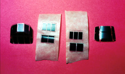
 There is a complete set of injection molded canopy
pieces and a set of vacuform front canopy pieces. The instructions are
clear and include several sketches of the craft showing some wiring
diagrams and views of the original pieces - these are great for
super-detailing. As I did the initial inventory of pieces problems
cropped up right away, the cowling pieces and the MG131 gun barrels were
badly warped and the decals were severely mangled. I contacted Squadron
immediately and had a complete replacement of the resin package and
decals within a few days. When they sent these pieces they also included
an additional set of canopies, which allowed me to make some revisions
that I'll explain later on. There is a complete set of injection molded canopy
pieces and a set of vacuform front canopy pieces. The instructions are
clear and include several sketches of the craft showing some wiring
diagrams and views of the original pieces - these are great for
super-detailing. As I did the initial inventory of pieces problems
cropped up right away, the cowling pieces and the MG131 gun barrels were
badly warped and the decals were severely mangled. I contacted Squadron
immediately and had a complete replacement of the resin package and
decals within a few days. When they sent these pieces they also included
an additional set of canopies, which allowed me to make some revisions
that I'll explain later on.
After painting the interior pieces and completing the basic assembly of
the main interior components I began to add detail derived from the
sketches. Control panels, seats and ammunition stores were set aside for
later detailing. The wiring was exposed inside the craft and consisted
of several main umbilicals. In order to simulate this I stripped the
wire from an old computer mouse. I took five strands of fine wire and
superglued them together and then painted the assembly light aircraft
gray. Through trial and error the wiring was bent to the correct shape
and the secured to the interior walls. Hold-down straps were fashioned
from small strips of foil cut from a wine bottle wrap and superglued in
place. These were painted RLM 76 to contrast to the wiring. Three
different umbilical sets had to be fashioned and installed before the
ammunition storage could be put in place. Once these had dried
completely the interior was washed with lampblack and dry brushed with
steel to highlight details. The instructions indicate that the lower
rear observation glass should be installed right at the beginning but I
decided to wait until the very end to do this. It meant a little more
work to trim the glass to fit from the outside but made overall painting
much easier. Now the gondola halves could be assembled.
The pilots and observers seats went together per the instructions but
the control column was lacking in some very noticeable detail. There is
a secondary level mounted on the column and an umbilical running from
the compass to the cockpit floor. These were created from some medium
fuse wire and computer mouse wire with foil hold down straps. This and
the seats were set aside for later installation. The rudder pedals also
lacked finer detail so I built the cable sheaths from phone wire
insulation superglued into place. These were set-aside after painting
also. The side console for the pilot went together right off the
directions but the main instrument cluster needed some extra work.
Since the back side was going to be visible and there were instrument
pods already molded in place I decided to install a wiring harness to
connect to the kit provided harness that ran up the starboard side. More
mouse wire and a ten power magnifying glass to get this installed. I
made the final umbilical long enough to lie overtop the kit umbilical to
create a smooth transition once complete.
Once all the subassemblies were completed, painted, washed and dry
brushed they were installed in the gondola. The main instrument panel
needed some putty to smooth out the fit to the super structure and the
cockpit seat didn't allow enough room for the pilots Armour to fit so
some minor placement adjustment had to be made there. The control column
seems to be a little oversized and had to be placed very carefully
between the rudder pedal extensions. The upper levers on the side
console interfered with the canopy on a test fit and had to be
repositioned. The bomb-site assembly is really a neat piece of work
consisting of three photo etched pieces with a lot of bends that looked
pretty difficult but was a piece of cake. The rear gun-mounting ring was
not a good fit and required a lot of putty to clean it up.
The original wing roots are molded for the "B" variant but conversion
pieces are included. The tail booms have a distinct ridge running down
the top and bottom and there was a sprue tab in the middle of every one
of them. This took some careful trimming to clean up and the injection
was incomplete here as well. This is a limited run kit so there are no
locator pins anywhere. I found that I could tape the main pieces
together with masking tape and then glue the seams with Tenax 7R being
careful to remove the tape before the glue got to it. The wheel wells
gave me a lot of trouble getting the glue joint cleaned up inside - had
to resort to the Dremel with a delicate touch.
While the larger pieces were drying I moved on to the landing gear
subassemblies. There is some really fine detail here but serious work
with a Xacto knife was required to clean up slag filling interior areas.
Each gear assembly consists of 13 individual pieces including some
photo-etched pieces. I added brake lines with hold- down straps but they
would have looked fine without any help. Here I used a Van Dyke brown
wash over dry brushed steel to accent the parts.
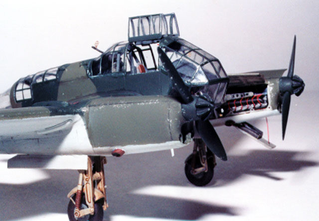
The Argus engines are very nice and include photo etched ignition
harnesses and rocker arm panels. The first sets of resin motor mounts
were destroyed in shipping but the second sets were fine. I ended up
with four complete engine assemblies, which got me to thinking. I wanted
only one engine open and wanted to use a second to replace the molded
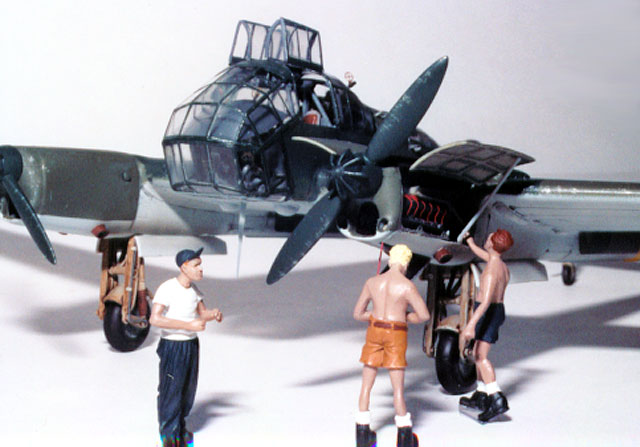
cowling/engine piece on the starboard side. A third engine was completed
and placed in a scratch built shipping case for diorama usage. The
original cowlings needed some surgery as the top; bottom and nosepiece
will be used. The Lower cowling piece has an access door that I wanted
to open on the exposed engine, it had to be thinned down and cut out
without causing damage to the surrounding material. I used a sanding
drum on a Dremel to thin the majority off and finished with 400 grit
automotive emery cloth. Once the engines were installed I added several
pieces of wire insulation and fuse wire to represent various control,
coolant and fuel lines feeding into the wing.
Painting,
Markings and Finishing
|
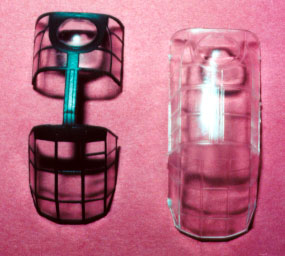
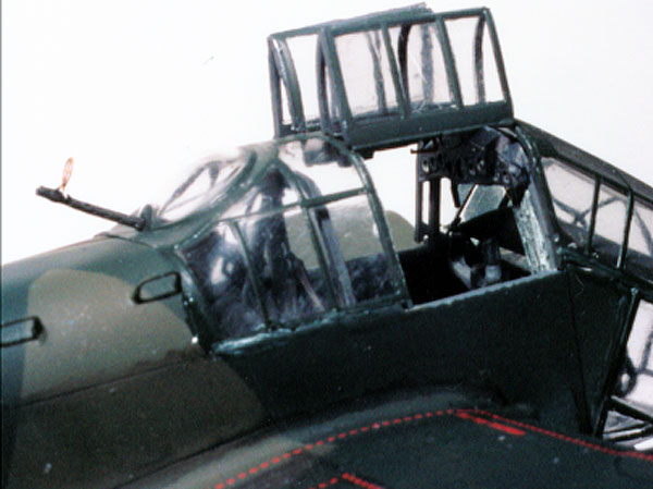
The rest of the assembly and painting were pretty much standard
until I got to the greenhouse. I wanted to open the top
access doors and had to spend quite a bit of research time before
running across a picture of a 189 sitting on an airstrip with the doors
open. They fold up and almost look like eyebrows when opened.
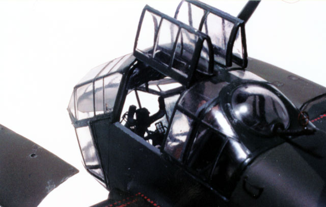
I cut out the doors from
one canopy piece, saving the main structure, and repeated this with the
second saving the doors. The main canopy becomes very fragile at this
point and it's best to get the upper instrument console mounted as soon
as possible to fortify the structure. The pilot's gunsight is way out of scale and has to be cut down considerably to fit
properly.
The decals are very good and snuggled down nicely with a little Micro
Sol solution. An acrylic paint mixed with soap provided the exterior
wash and the kit was finished off with a coat of Testers Dull Coat
Lacquer.
This is the first kit from MPM that I have
built and it really impressed me.
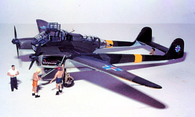
This is not something for
the beginner but if super detailing is what you want to do, this is a
great place to start.
Click
the thumbnails below to view larger images:
Model, Images and Text Copyright © 2002 by
Matt Swan
Page Created 05 June, 2002
Last Updated 04 June, 2007
Back to HyperScale
Main Page
Back to Features Index
|
 Home
| What's New |
Features |
Gallery |
Reviews |
Reference |
Forum |
Search
Home
| What's New |
Features |
Gallery |
Reviews |
Reference |
Forum |
Search