|
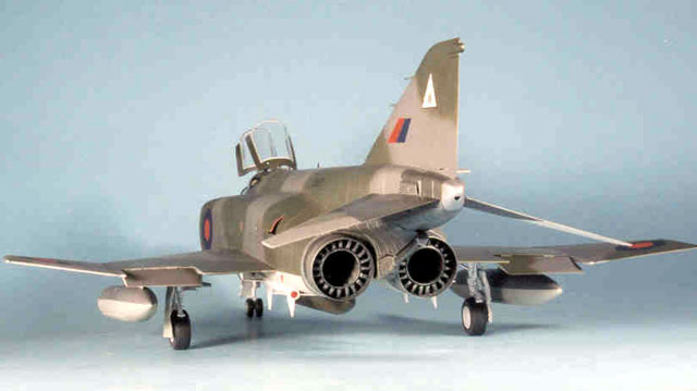
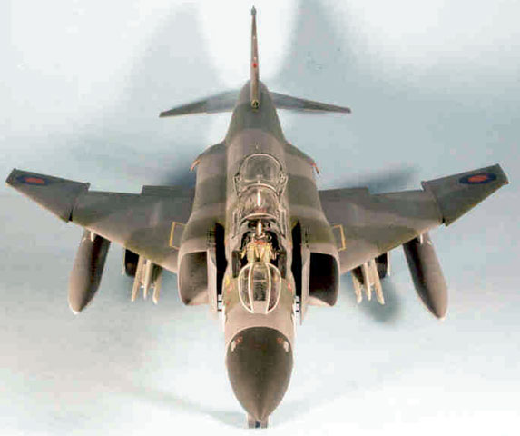
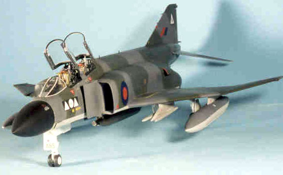
FGR.2 Phantom
in 1/32
Scale
by Frank Mitchell
|
|
|
FGR.2 Phantom |

Tamiya's
1/32 scale F-4J Phantom is available online from
Squadron.com
When conventional wisdom insists that a conversion
cannot be carried out, it can become an irresistible challenge. That
being the case, when I was able to score a Tamiya F-4J from Model Expo
for only $39.95, I decided that the time was ripe to see if I could turn
it into a British Phantom.
Finding decent drawings was not all that easy. I ended up using small
drawings from a number of sources, the drawings published in Scale
Models International many years ago, and my technique of enlarging
photos to the scale I need. When all of these agreed on a shape or
dimension, I felt fairly safe in using it.
Note: Some of the following will sound (read?) harder than it really is,
so check the photos for clarification.
Converting
Tamiya's F-4J into an FGR.2
|
Since the major change to the British F-4 was the engines, that was
where I started.
Engines
I found that the diameter of the exterior exhaust
nozzle of the Spey was 1 3/8” in 32nd scale. I turned molds for those
and for the very visible petals of the exhaust from some scrap hardwood
Two sets of each were produced by vacuum-forming. The outer shrouds were
trimmed from the plastic and finished to the correct length of ½”. The
“petal” pieces were cut from the plastic, scribed, and the center hole
opened.
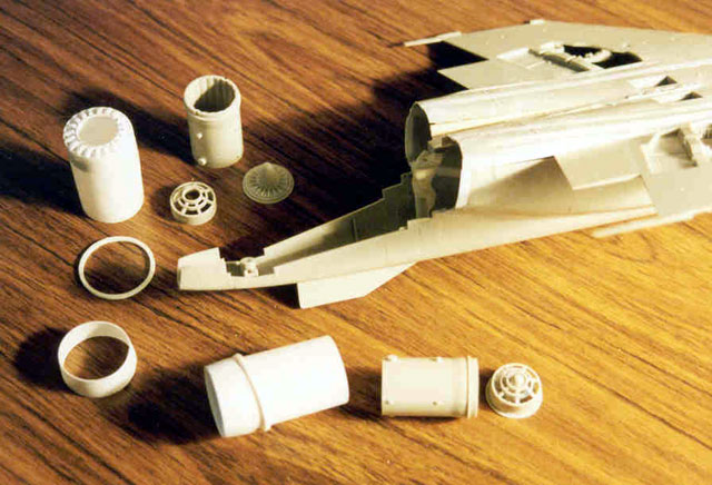
Each Spey engine had twenty petal actuators which were made by sanding a
long piece of plastic strip to the proper shape (as seen from the side).
Then, a simple jig was made from scrap balsa and forty pieces were
sliced from the strip, each about 1/16” wide. A piece of twenty thou
styrene was molded around a convenient form to just fit over the “petal
piece” and once it was glued in place, the actuators were positioned and
glued. All this sounds harder than it is--see the pictures. The parts of
the engine that were visible through the exhaust were taken from the
scrap box and the kit and fitted to the inboard ends of the exhaust
tubes.
Now that I had the “engines” built, I could begin making the fuselage
fit around them.
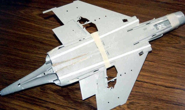
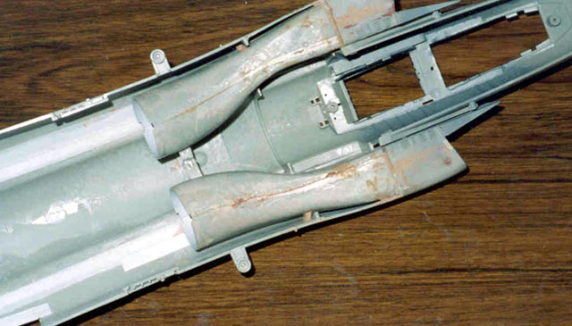
Fuselage Modifications
Cuts were mapped out along the top of the large
fuselage molding from the inner aspects of the intakes to the exhaust
openings. 3/16” wide styrene strip was spliced between the cut pieces.
Similar cuts were made along the bottom fuselage section and these were
placed to avoid airbrakes, wheelwells, etc. Likewise, the separate,
outer intake pieces were split along both the top and bottom surfaces
and the same 3/16” strip glued in place.
Now, using my thinnest saw blade, the inboard edge of the inner flap on
the bottom fuselage molding was separated from the fuselage, which
allowed the rear portion of the bottom fuselage to be bent down
slightly. A strip of styrene that tapered from 3/16” at the exhaust end
to 0 was cut and glued onto the top edge of the bottom fuselage molding
beginning at about the point where the hinge of the inner flap meets the
wing.
Click
the thumbnails below to view larger images:
When the upper and lower fuselage sections were
then tightly taped together, the exhaust openings were the correct width
and depth (but not yet the correct shape) to accept the new engines, and
the bottom of the fuselage angled down properly, as did the engine
exhausts. The intake openings were also the correct 20% larger than the
U.S. Phantom, which gave it the “broad-shouldered” look that
distinguishes the British Phantoms.
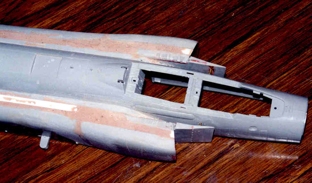
Intakes and BDR Panels
Now came the hardest part of this model: the
#%$&$@* Tamiya intakes. This was my second F-4, so I knew how bad they
were, but on this one, life was even more difficult because of the
widening which required, of course, that the inner intake pieces had to
be widened as well. Since I was not about to use FOD covers, we will
draw a curtain over the next several days only revealing that with a
great deal of epoxy, lots of putty and primer, and no end of
aggravation, I ended up with intakes that were more or less smooth. The
engine forward faces (which were modified to look a bit more like Speys
than J-79s) were also intact and visible. In case you wondered, I had a
set of Seamless Suckers, but because of their wall thickness, starting
with them would have been even more work than were the kit pieces.
The next big hassle was getting rid of all the battle-damage repair
panels that Tamiya faithfully reproduced, and they are all over the
place.
Assembly
Except for the areas around the exhausts and the
main horizontal fuselage seam, the fuselage and wings were then filled
with epoxy, smoothed, primed, and re-scribed as necessary. A fair amount
was needed, and it was easier to do now than before the two halves were
glued together.
Since I had decided on building an FGR-2, which did not have the F-4J’s
slotted stabilators, the kit pieces were cut from their central
structure and surfaces from a Revell RF-4 were adapted (The RF had long
since lost its nose to become a “Tamiya” RF-4). The Revell stabilators
were attached to the Tamiya center section by means of brass pins so
they could be added after painting was complete. The angle of anhedral
was also slightly reduced as they were on the British Phantoms to clear
the exhaust from those big engines.
The landing gear was essentially out of the box but the parts were
detailed as necessary.
Work now shifted to the interior, which was put together by mixing and
matching pieces from a Cutting Edge F-4E update set, CAM seats, a bunch
of the kit parts (some modified, some not), a fair number of parts from
an Eduard F-4 set, and a bit of scratch building. It helped that I had
started from an F-4J kit, since the interiors had some similarities.
Once all the pieces were gathered together and fitted, they were painted
and detailed in the usual way.
The Moment of Truth came when the bottom wing/lower fuselage molding was
permanently attached to the upper fuselage. Everything went well and the
look I was after began to appear.
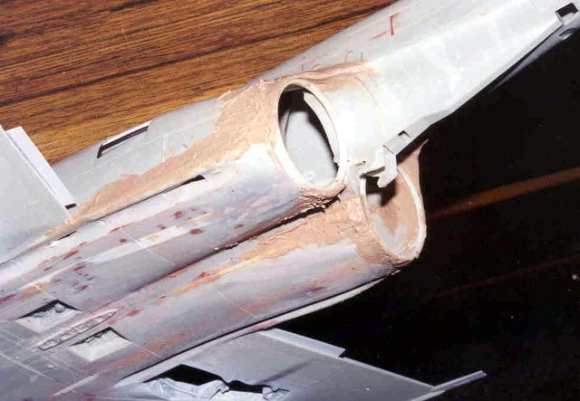
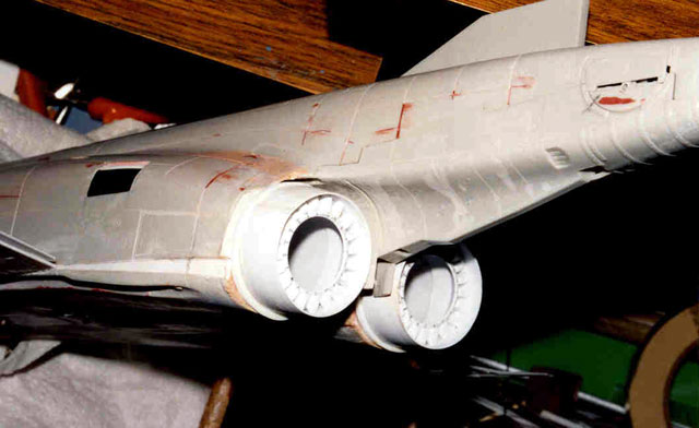
To make sure that my new “engines” fit into the fuselage properly, I had
cut two rings from 1/16” thick styrene. These were shaped to fit tightly
around the bodies of the exhausts. The rings were slipped over the
exhausts without glue, and the units were inserted into the fuselage.
The rings were carefully tacked in place with super glue gel, and the
exhausts removed. Filled epoxy was then applied over the fuselage and
the rings. After sanding and smoothing, I ended up with two nice round
holes that allowed the “engines” to be glued in place after painting was
complete. Again, check out the pictures and all will be clear.
The tailhook still fitted fine, but I did need to make up a new piece to
cover the bottom of the fuselage beside the exhaust nozzles.
The kit outer wing dihedral is about twice what it should be. Therefore,
I glued strips of twenty thou styrene onto the inboard edge of the
upper-outer wing half and sanded it to match. That was really all it
took—the dihedral is now right, and the wing fold still fits fine.
A CAM SUU-23 cannon pod was added, as were two Sparrows in the rear
wells, dummies in the front wells, drop tanks, and empty inner pylons
(it was easier to do that than fill the holes and re-scribe).
When all this was done, the usual filling, sanding, priming, and
re-scribing routine began until I was satisfied that the model was ready
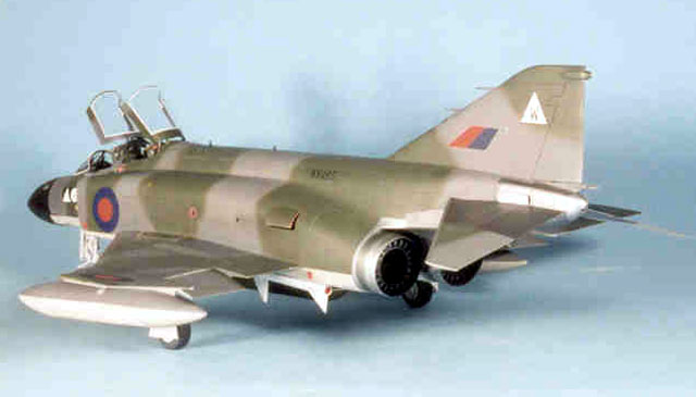
for paint. By now, I had decided on the specific bird I wanted which
meant that the final scheme would be mat Dark Sea Gray (or “grey”,
depending on which side of the pond you are), Dark Green, and Light
Aircraft Gray. These were applied using Gunze, and the paint was covered
with a coat of Future in preparation for the decals. The natural metal
sections were applied with Testor’s metal paints.
The decals were a mix of roundels from a Hunter sheet, and slightly
reduced squadron markings from a Tornado sheet. Serials were
enlarged/reduced from a 48th Phantom sheet. Miscellaneous decals came
from the decal box. All went well if you don’t count dropping the model
half-way through the decaling which ripped off a few small pieces and
broke both wing joints.
Weathering, what there was of it, was applied with chalks, some thinned
black/dark gray on the lower surfaces, and even a bit of pencil.
So, there it is. You can decide whether the conversion was successful,
but it was an interesting modeling project, and I am satisfied with it
(or at least, I will be until Tamiya announces one, which, with my luck,
will be next week; it could then be a companion to my built-the-hard-way
24th Sea Harrier).
Click the thumbnails below
to view larger images:
Model, Images and Text Copyright © 2002 by
Frank Mitchell
Page Created 02 July, 2002
Last Updated 04 June, 2007
Back to HyperScale
Main Page
Back to
Features Index
|
 Home
| What's New |
Features |
Gallery |
Reviews |
Reference |
Forum |
Search
Home
| What's New |
Features |
Gallery |
Reviews |
Reference |
Forum |
Search