|
F-15E Strike Eagle
by Douglas K. L. Chan
 |
|
F-15E
Strike Eagle |

Tamiya's
1/32 scale F-15E Strike Eagle is available online from
Squadron.com
Before I go into the detail of construction, I would like to thank CC for
giving me a push to make this model.
I showed a photo of the Mudhen to my girl last year and asked for her opinion.
Amazingly she said “it is good looking” and she would buy me a model. Woo, that
was really unexpected. So, I got one and built it. Thank you CC, I love you so
much !
Okay, I know you guys are getting bored - let’s get to the point.
|
Tamiya's 1/32 Scale
F-15E |
There are several kits available in the market. The very common and economic
ones here in Hong Kong are Hasegawa and Academy in the scale of 1/48. However,
these two kits are not accurate at all (bulged main landing gear doors, pylons
underneath CFT, cockpit, etc.). You will need to do a lot of modification on the
model.
Then it is Revell and Tamiya in the scale of 1/32. Revell is neither popular in
Hong Kong. So in the scale of 1/32, the only choice is Tamiya. Fortunately, the
price of 1/32 kits has dropped considerably in this two years. The kit costs
only HK$400 i.e. US$51.
The box is quite big in size, so make sure you have your love one’s support or
you have her fully informed, because there is no way that you can sneak the big
box past her.
Opening the box you will see the upper and lower fuselage; 11 sprues of plastic
parts; a set of screws, nuts, rubber tires, and metal landing gears; one sprues
of clear plastic parts for the canopy and navigation lights; two sheets of
decal; and one piece of RBF sheet.
The instruction booklet is of A4 size, 28 pages, which is really informative for
making an out-of-box kit. A better one should be the Tamiya 1/32 A6M5 Zero.
I was not building the Strike Eagle in the out-of-box way. As a matter of
fact, I added every add-on parts I could find. These add-on parts included:
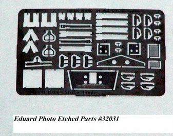
- Eduard photo etched parts # 32 031 F-15E Strike Eagle 1/32 scale detail
set for Tamiya kit
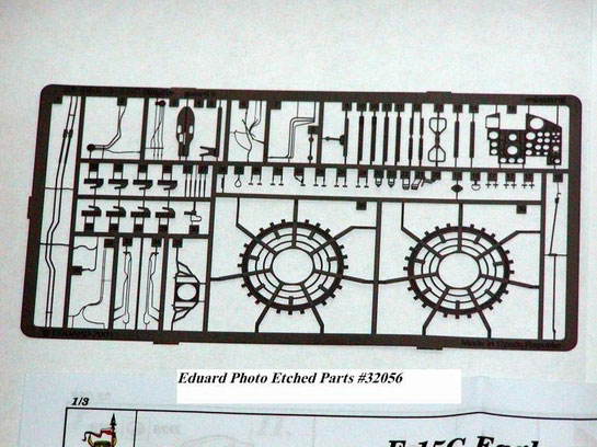
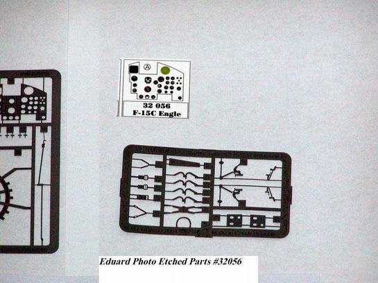
- Eduard photo etched parts # 32 056 F-15C Eagle 1/32 scale detail set for
Tamiya kit
- The Gunsmoke Range, Flightpath, GBU-10C Laser Guided Bomb Set
- The Gunsmoke Range, Flightpath, 1/32nd Scale AIM-120 AMRAAM Missile Set
- The Gunsmoke Range, Flightpath, 1/32nd Scale AIM-9L/M/R/S Sidewinder
Missile Set
- Clear plastic lens of 2.5mm diameter
Click the thumbnails below to view
larger images:
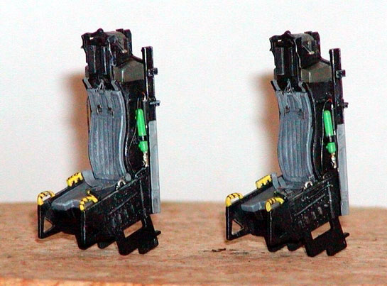
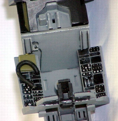
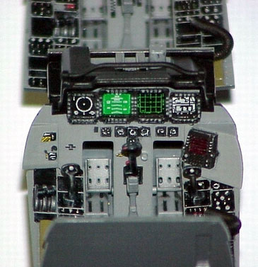
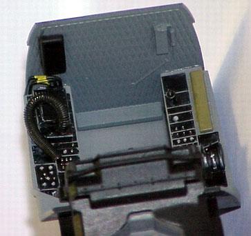
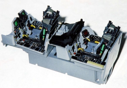
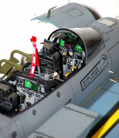
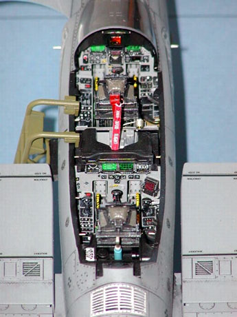
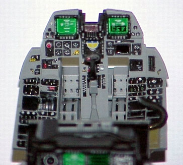
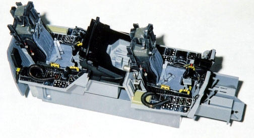
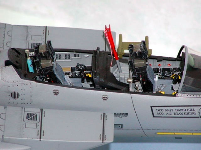
Cockpit
 As
usual in every model aircraft, the very first thing is the construction of
cockpit assembly. There was no problem assembling the kit parts. As
usual in every model aircraft, the very first thing is the construction of
cockpit assembly. There was no problem assembling the kit parts.
The hose on both sides of the original seat was replaced by copper wire. Seat
belts from Eduard set #32031 was added to the two ejection seats. Pedals and
instrument panel supports from Eduard set #32031 were also added.
I’ve scratch built the oxygen supply hoses, and the canopy lock pins in the
cockpit. Also, some wiring, gas hose coupler, and structural parts were added.
Reference was made to the walkaround photos in ARC and Verlinden Lock On No. 22.
Click the thumbnails below to view
larger images:
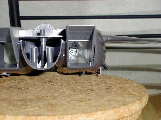
Intake Ducts
The intake ducts assembly is of upper and lower half. Once glued there was a
noticeable seam in both sides of the ducts. The only way was to apply putty, let
it dry for a few days, sand it until there was no seam at all.
A lot of effort will be saved if there was an after-market resin one piece
intake duct. I hope one will make this available. This is one of the two critics
I have on this kit.
The finished ducts were then sprayed with flat white. When it is completed
dried, a sponge of appropriate length was inserted into each duct to cover the
white color (make sure the one and a half inch length near the intake is
uncovered). Then the body grey color was sprayed. When the grey color was
completely dried, the sponge was removed. This was how I made that two tone
color inside the intake duct. Sponge offered the advantage that it can be shaped
easily. By using it there is no need to do the difficult masking on the inside
of the duct.
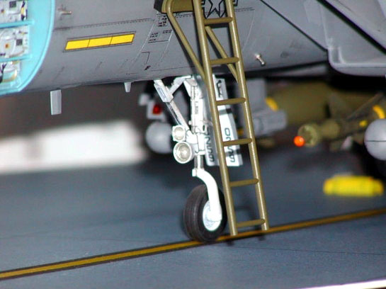
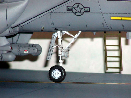
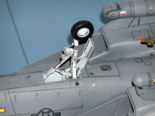
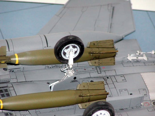
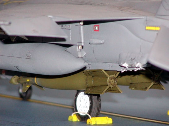
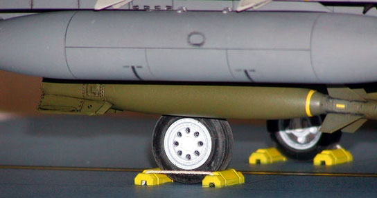
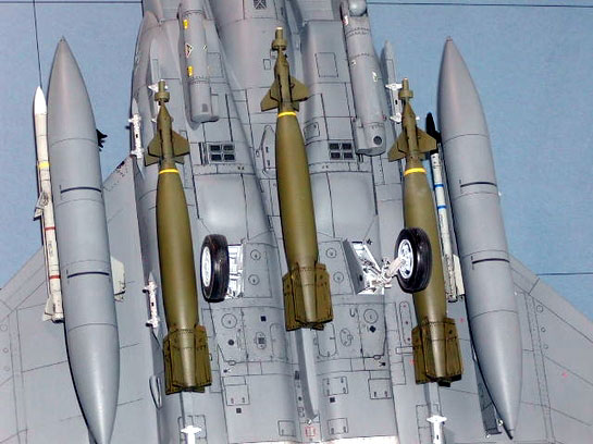
Landing Gear
The whole model is quite heavy, particularly when carrying after-market resin
laser guided bombs. Therefore white metal landing gear is a must to provide a
reliable support. Also, the white metal landing gears duplicated quite well of
the real thing. I should have added a brake hose for the main landing gears.
However, the main legs are not easily visible as the view is being blocked by
the laser guided bomb. So, I gave up adding the hoses. All three landing gears
were sprayed flat white and then a black color wash.
Click the thumbnails below to view
larger images:
Wing/Fins
The main wings, tailerons, and vertical fins fitted quite well. A little
sanding was needed but that was all. They were all sprayed with the body grey
color.
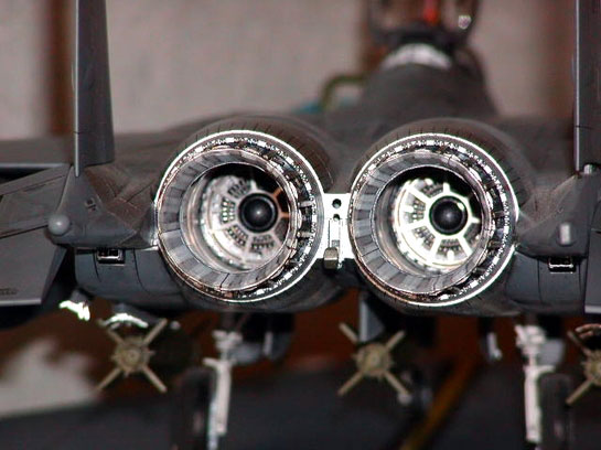
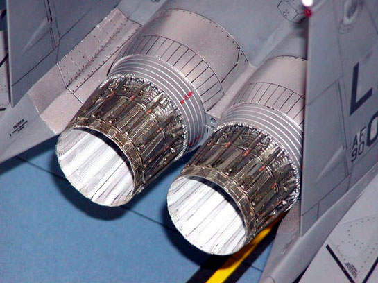
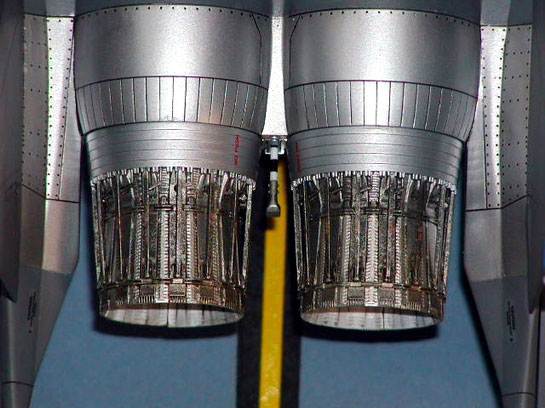
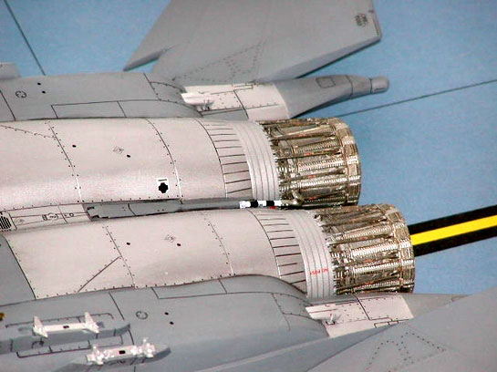
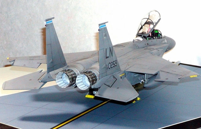
Exhaust Nozzles
Here comes my second criticism. Similar to the induct ducts, the exhaust
ducts are also assembled from a upper and lower half. So there were also visible
seams on the inside of the part. However, because of the recess on the inside of
the exhaust ducts, there was nothing I could do to cover those seams.
The exhaust nozzles fitted well. It was just a little tired to prepare the 30
identical small linkage and turnkey features. But, it was worth the effort.
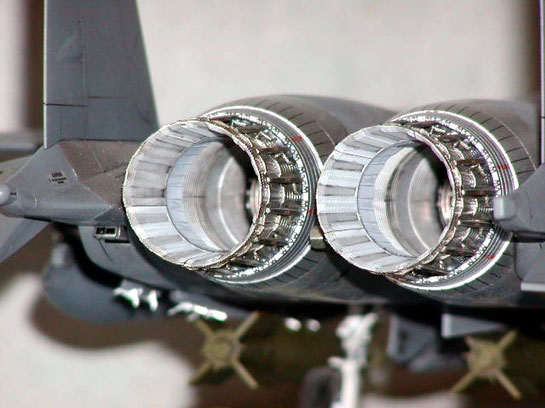
The inside of the finished exhaust ducts and the exhaust nozzles were sprayed
flat white. Then, a black color wash was applied for the effect. When the inside
was readied, it was sealed with masking tape, and then the external was sprayed
with a mix of metallic grey and clear orange. A dry brush of silver was applied.
Click the thumbnails below to view
larger images:
Radar
The radar assembly also fitted well. However I did a modification on the
radar disk and the support structure. First the plastic antenna on the radar
disk were removed, the radar disk was then sprayed with Dark Yellow, then the
letters “RADIATION HAZARD” were transferred, the photo etched T-shape antenna
from the Eduard set #32056 were fixed onto the radar disk by CA glue.
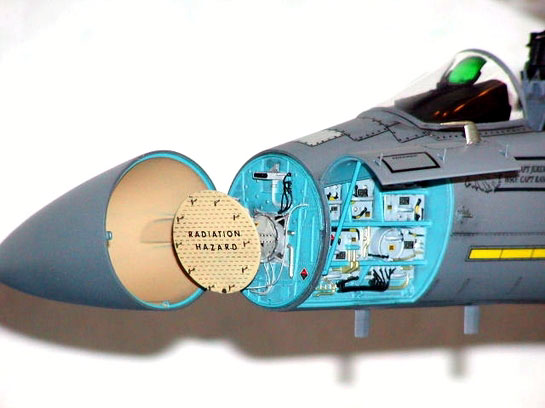
Then the wiring around the radar support structure were added by copper wire.
After the application of decals and wash, the assembly looked quite realistic.
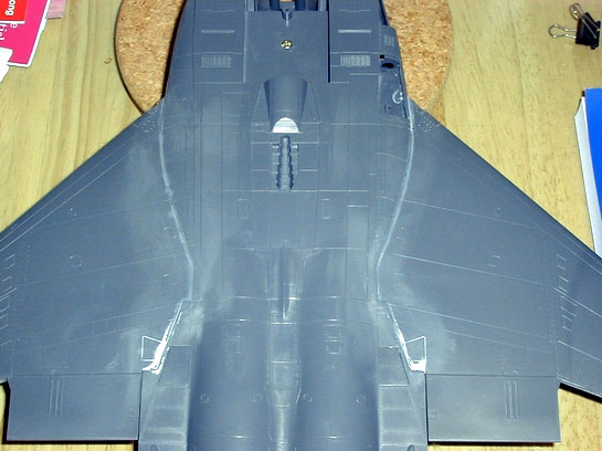
Body
After the installation of the intake ducts onto the lower body, the upper
body was fixed to build up the main body. Because of the variable intake, extra
care was taken, particularly while the forward portion of the CFT was glued. CA
glue was used to save time for curing. Then the forward fuselage was attached to
the main body. Only little putty was needed for the joint, I was quite satisfied
with the result, bear in mind that the model is quite big in size. After that,
the wings were attached to the main body. Again, CA glue was used. For the wing
joint, putty was not necessary. The cured CA glue already served the same
purpose. So I sanded it and it was finished. Holes of dia. 0.5mm were also
drilled on the body to simulate screw marks. Panel lines removed were
re-inscribed.
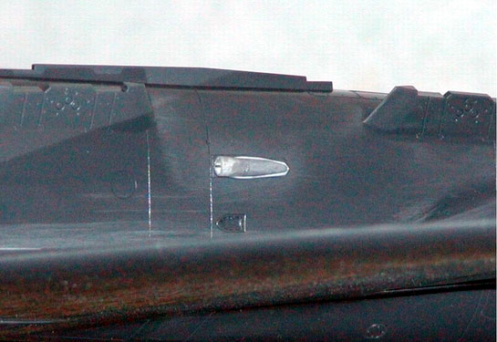
There should be an air vent near the wing joint. It is strange that Tamiya
missed this part. By the time I built this kit, I had to scratch built this
little part. I used a 3 mm tube, pressed to oval shape, then attached it to a
strip. A small photo etched plate is inserted inside the oval tube as it should
look like in the real thing. However, we now have the add-on part from Cutting
Edge Modelworks.
Click the thumbnails below to view
larger images:
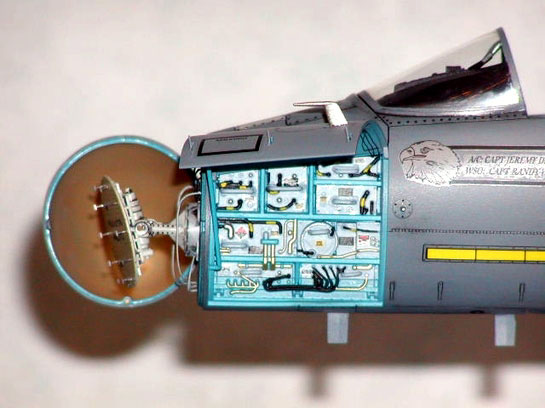
Equipment Bay
It is quite boring for such a big size model if there is nothing special.
Opening the equipment bay will solve this problem. The equipment bay is nicely
molded except the handle for the equipment is molded solid. So, I cut the molded
handle, drilled holes and inserted copper wires to make the handle. The
equipment bay was colored as instructed in the booklet. The placard was added to
make it looked more realistic.
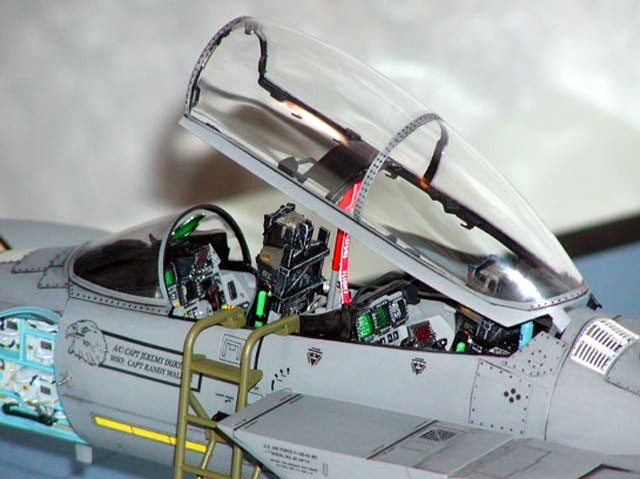
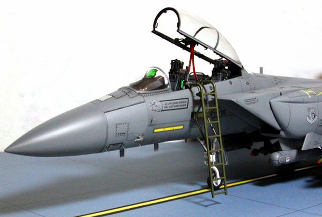
Canopy
The canopy is nicely molded with the frame separately from the clear part. As
usual, there was a seam along the doom shaped part, so I used the usual
technique to remove it (file, sand with #400, #1000, #2000, then rub with #3000
paste, and then apply a coat of Tamiya wax). Holes of dia. 0.5 mm were drilled
to simulate the screw marks on the canopy frame. The tapered canopy locks from
Eduard set #32031 were attached to the canopy frame by CA glue. The inside of
the canopy frame was hand painted with flat black. The outside of the canopy was
masked with Eduard Express Mask SL011 and then the frame was sprayed with the
body grey color. The Eduard mask proved to be a very good tool.
Click the thumbnails below to view
larger images:
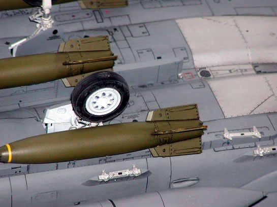
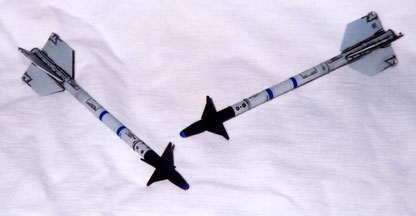
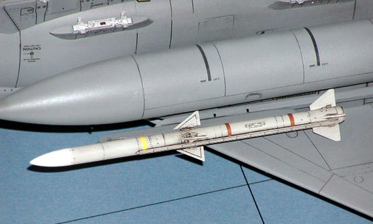
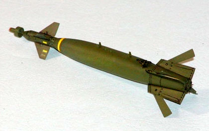
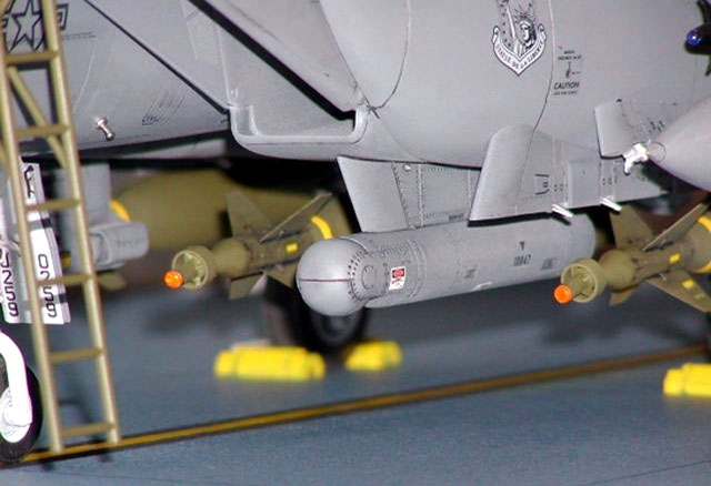
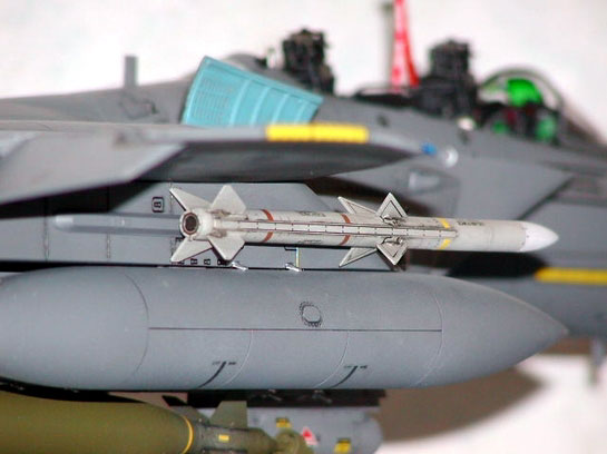
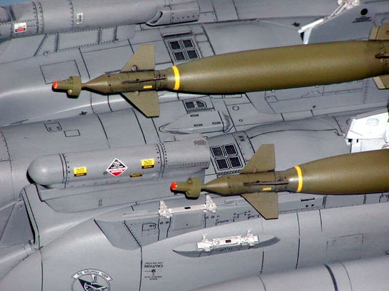
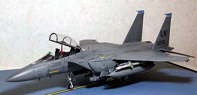
Armament
The standard armament provided in the kit is AIM-9, GBU-10, and cluster
bombs. However, the usual loadout in the recent missions shall be AIM-9,
AIM-120, and GBU-10/GBU-12. So, I replaced the original armament with Gunsmoke
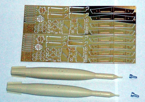
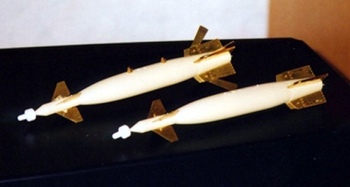
parts. The detail of the Gunsmoke AIM-9, AIM-120, and GBU-10 is amazing. The
missile body and the bomb body is of resin material, all the control fins are of
photo etched parts. One thing I do not like is the laser seeker which is cast in
white metal. It is not quite accurate so I used the seeker provided with the
kit. Other that this minor issue, the Gunsmoke parts are highly recommended.
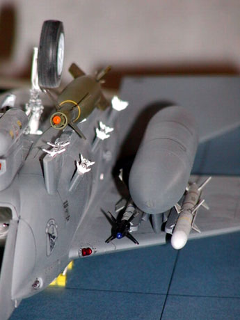
There was one more modification for the armament. I filed the front part of the
AIM-9 and the GBU-10 and then fixed a clear lens (blue for the AIM-9 and amber
for the GBU-10) for the IR seeker and the laser seeker respectively. The result
is very good.
Click the thumbnails below to view
larger images:
The color of the Strike Eagle is of a simple grey color. In the Tamiya
instruction booklet gunship grey is specified. However, I feel it is too dark.
After several color trials with some scrap model, I decided to use Tamiya AS-10
Ocean Grey, which looked more or less the same as the reference photos I have.
Due to the big size of the model, spray can was used. I used almost three cans
of AS-10 for the whole work.
When the grey color was completely dried, areas other than the engine area was
masked, then the engine area was sprayed silver. The panel lines were later
highlighted with thinned black color enamel.
|
Decals, Weathering and
Finishing |
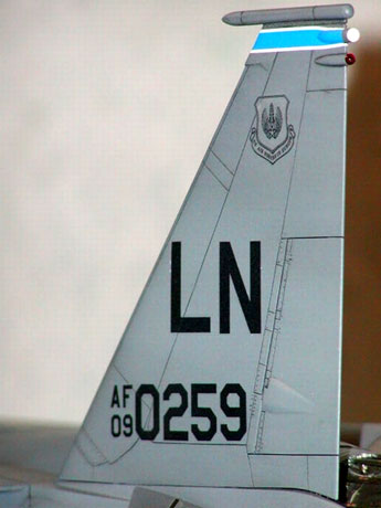
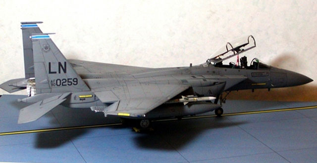
The decals supplied with the kit are for the squadrons stationed at
Seymour-Johnson AFB (SJ). I preferred to used an after-market decal for the
492th Fighter Squadron stationed at RAF Lakenheath (LN), as my references are
all of the LN planes. Of course now you guys have another choice from TwoBobs
The decal I used is from Astra Decals ASD-3201b. The quality of the decals
seemed not quite well as I noticed there was some “silvering”. May be it is
because of the dark base color (grey), but it just doesn’t look quite good.
However, it is all too late to switch to another marking.
Unlike Navy aircrafts, weathering is kept to a minimum because I never seen a
photo of the Strike Eagle which is dirty.
When everything was set, I sprayed a coat of flat clear to protect the decals
and to keep the body color consistent.
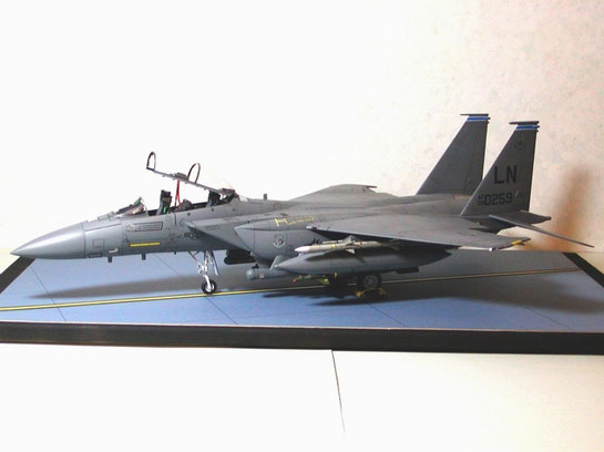
The display base is simple to make. A wooden stripe, a cardboard and a glass
cover. Lines were drawn by ink pen on the cardboard. The cardboard was then
fixed onto the wooden stripe by UHU glue.
I’ve heard people say this is a once in a lift time kit because of it’s size
and cost. After I built it, yes, I agreed it is so.
I started working on this model at the end of November 2001. I finished it at
the end of May 2002, a total of six months. For a kit of this size, the details
as molded are very impressive. However, there is still room for extensive
detailing.
This is my first ever 1/32 kit and I don’t think I will go back to 1/48 again.
1/32 is really fun and I enjoyed building in such a scale, particularly with the
support of my girl CC.
I hope you guys like my Strike Eagle and I am glad to share with you all my
experience.
Once again, thank you my love CC !
(a) Thanks Twobobs for sending me a photo of a laser guided bomb hanging on
the forward pylon under the CFT (the one in their F-15E MO decal instruction
sheet)
(b) Thanks Gunsmoke for granting me the permission to scan their instruction
sheets for AIM-9, AIM-120, and GBU-10
Click
the thumbnails below to view larger images:
Model, Images and
Article Copyright © 2002 by Douglas
K. L. Chan
Page Created 21 September 2002
Last updated 04 June 2007
Back to HyperScale Main Page
Back to Features Page |
 Home
| What's New |
Features |
Gallery |
Reviews |
Reference |
Forum |
Search
Home
| What's New |
Features |
Gallery |
Reviews |
Reference |
Forum |
Search