|
F-111C/AUP
by
Anthony Papadis
 |
|
F-111C/AUP |

Hasegawa's 1/72
scale EF-111A is still available online from Squadron.com
This model was built as a farewell presentation to the outgoing CO of
501Wing, RAAF Amberley in 2000.
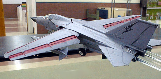
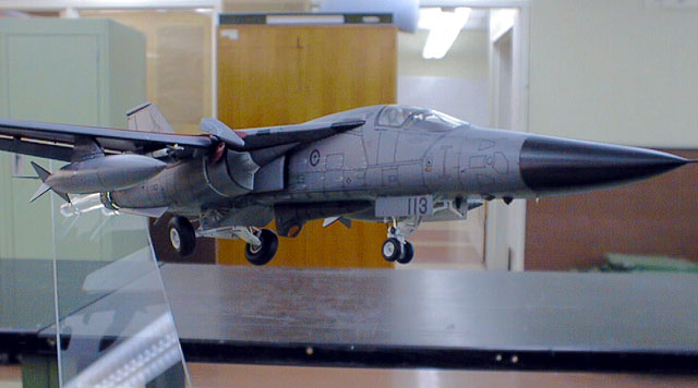
The model depicts a 1 Squadron F-111C/AUP, as it would appear on approach to
land. The model was based upon the excellent 1/72 Hasegawa F-111C kit (K33)
which is becoming harder to find these days. The kit was assembled mostly from
the box, however some ‘tweaks’ were added, and some surgery was carried out.
Construction generally followed the kit instruction sequence, however in order
to make masking and painting easier, I left off the air intakes, undercarriage,
afterburner cans, Pavetack pod and ordinance until after the fuselage was
painted, decalled and weathered. I also painted the wings separately, attaching
them after the fuselage was completed.
The cockpit was assembled straight up, however RAAF F-111’s feature black lamb’s
wool covers with black seatbelts. The buckles are a metallic blue. The
instrument panel decal depicts a pre-AUP (Avionic Update Programme) bird and is
technically incorrect, however unless you know what to look for, it will not
really matter in this scale, especially when the canopies are down and aircrew
added. These are Hasegawa figures which had their helmets sanded to depict the
newer, lighter HGU-65 series of ‘bone domes’
The instructions were followed until step 7, where the air intakes are attached.
In conditions of low forward speed, e.g on the ground and at high AOA (angle of
attack), the engines don’t receive enough air through their intakes,
consequently the intake cowls are of the ‘transition’ type. This means that they
move forward under hydraulic power to open up an approx 8” ‘slit’, which allows
more air to pass into the engines. This is typically seen when the aircraft is
taxying and on approach to land. To reproduce this, it was simply a matter of
attaching the translating cowls(D5, D4) about mm forward of their normal
position, and voila ! translating cowls!!.
The next point of interest is the landing gear. As with most aircraft in flight
, the undercarriage ‘sags’ when the aircraft’s weight isn’t compressing it. To
reproduce this will require a little bit of surgery. I began with the nose
strut. Part A14 had its oleo cut off, and replaced with a section of appropriate
diameter aluminium tube, which was glued into holes that I drilled with a pin
vice. The nose wheel steering (NWS) rod, part B12 had a length of plastic rod
glued to replace its oleo (which incidentally is painted a green zinc chromate
colour and not silver as the instructions state!)
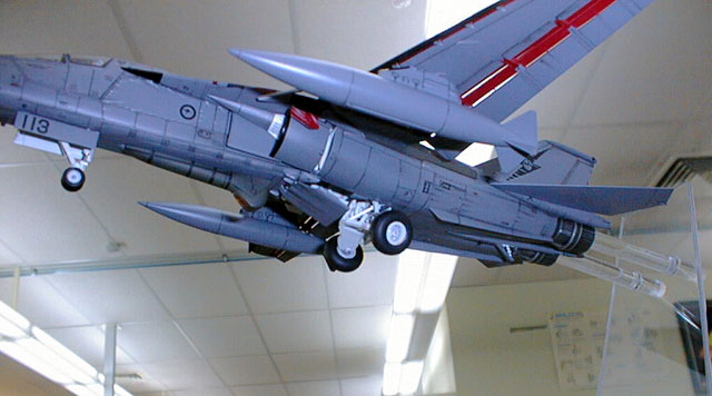
Now, the main gear. I began by carefully cutting off the main wheel axles
from B29, and put these aside. Next, the two outer sections of B29 were cut from
the centre section. On the aircraft, these outer sections fold downwards in
‘clapping’ motion. in flight, they hang down at about a 50 deg. angle. Once cut
apart at the hinge points, they were carefully re-glued at about a 50 deg.
angle.The retraction struts, parts G5 had their oleos cut off and new, longer
ones attached from plastic rod. The length of these were cut to suit. On the
gear bay firewall, the tie rods (the thin rods which stick out of the triangular
base of A18) were carefully ‘shaved’ off and glued at the same angle as the
outer pieces of B29, so that they are parallel with them. The remaining pieces
of the main gear, B16, B14, and B7 were now attached, as well as the main wheel
axles (removed earlier), and left to harden overnight. In the morning the whole
assembly was examined and was found to be remarkably robust considering the
cutting and gluing that took place. The wheels were painted and attached to the
now painted maingear assy. Incidentally, ignore the instructions direction to
paint the hubs silver, they are semi gloss white and very dirty, especially on
the inboard side due to the brake dust etc. The gear door B28 was attched last
after it was painted. Phew!
The remaining construction followed the instructions.
Because the kit was to be depicted in-flight, I had to come up with a way of
mounting it so that it would be suspended in the air. I decided to use to acylic
rods, glued into the afterburner cans, which in turn mounted into an ‘L-shaped’
piece of Lexan plastic, which in turn was mounted to the display base.
I cut the ends off the engine liners (G13) and epoxied the two pre-cut
lengths of rod into them. when all was complete, the afterburners were assembled
and these epoxied to the rest of the aircraft.
The current RAAF camouflage consists of overall Gunship Grey, FS 36118. I used
Gunze Sangyo paints for this as they are a good match and dry semi-gloss,
eliminating the need for gloss-coating. The noses of the aircraft can vary from
semi-gloss black when new to almost matt black after heavy use
The kit decals depict the previous South East Asia scheme. I replaced these with
the Aussie Decals set. These are mostly accurate, however there is a major flaw
in the tail emblems for 1 Sqn aircraft. The emblem consists of a Kookaburra (an
Australian native bird similar to a big Kingfisher) diving down over a Maltese
Cross, all inside a black Lightning Bolt.
The problem is, the Maltese Cross should be perpendicular to the horizontal
when the Lightning Bolt is placed on the tail. If you do this as the markings
are supplied the Lightning Bolt is rotated too far forward. If you correctly
orientate the Lightning Bolt, the Maltese Cross is rotated backwards. I
carefully cut around the Cross/Kookaburra emblem with a brand new scalpel blade
and applied them separately to the Lightning Bolt to ensure correct orientation.
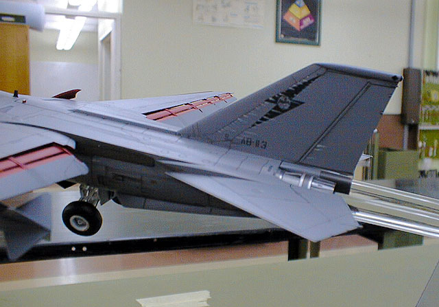
The 6 Sqn decals are correct. The sheet allows the builder to depict any
aircraft serial number. so I chose A9-113 (lucky 13!).
I wanted to depict an aircraft which was a workhorse, so it exhibit heavy
staining and wear. I applied a lighter shade of the grey to areas around the
cockpit, fin and upper wings, typically where the aircraft paint fades the most
heavily. Next a wash as applied, I like to use oils. The staining was also
accentuated around the underside of the aircraft, especially aft of the main
gear.
You may have noticed by now all the grey streaks. Technically referred to as
reversion, this occurs when the two part caulking sealant breaks down over time
and under the heat of supersonic flight and then proceeds to ooze out of rivet
holes and panel lines, following the local airflow pattern back to form these
smears. The aircraft are spotless after they come out of depot servicing but
soon accumulate dirt and grime, hydraulic oil and fuel leaks. Usually, following
a supersonic flight, paint will start to peel off, and the sealant or “goop” as
we like to call it begins to seep out. High wear areas also include the intake
cowl lips, the outer wingtip leading edges and splitter plate leading edges,
which are normally bare metal due to the severe aero-erosion.
A word on the stores. as usual with most Hasegawa kits, this kit comes mostly
unarmed, with the exception of the Durandal runway denial stores. The RAAF never
bought these so they are consigned to the spares box. The kit does supply the
BRU’s (bomb racks) as well as the ‘jugs’ or drop tanks and the shoulder mounted
AIM-9 missile launchers. I wanted to depict the aircraft as having come back
from a heavy bombing sortie, so the bomb racks would be empty. I also loaded a
couple of AIM-9l ‘heaters’ for self-defence.
The Pave Tack pods on F-111 aircraft will eventually all be painted the same
overall Gunship Grey as the rest of the aircraft. In the meantime, there are
still some black painted pods, and even some olive drab ones, bought as
additional spares. The black pods have white datum lines on them, and the grey
and olive ones have black datum lines. I wanted to inject a bit of colour (if
olive drab could ever be described as colourful), so my Pave Tack pod is an
olive drab one.
The undercarriage gear, wings and afterburner sub-assemblies were now
attached.
Although the surgery sounds extensive, it was actually more complex to
describe than to carry out, and I really enjoyed the change from ‘static’ poses.
I believe that any moderately experienced builder could carry out this
conversion.
Model, Images and
Article Copyright © 2002 by Anthony
Papadis
Page Created 12 January, 2002
Last updated 04 June, 2007
Back to HyperScale Main Page
Back to Features Page |
 Home
| What's New |
Features |
Gallery |
Reviews |
Reference |
Forum |
Search
Home
| What's New |
Features |
Gallery |
Reviews |
Reference |
Forum |
Search