|
Douglas DB-7
Boston
by
J.D. King
|
|
|
Douglas DB-7 Boston |

HyperScale
is proudly supported by
Squadron.com
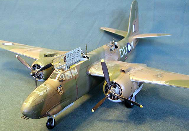
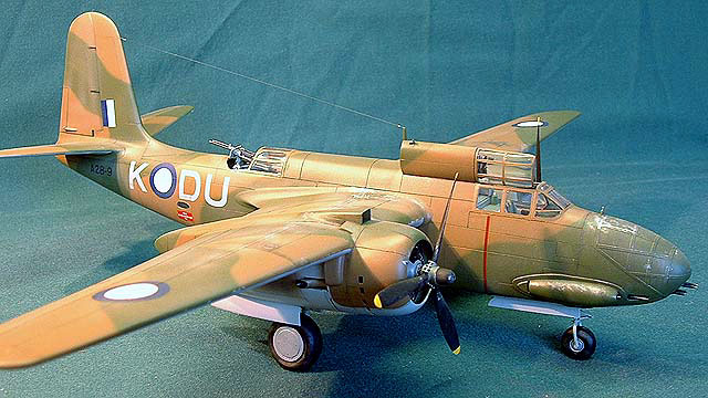
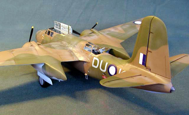
Here is a 1/48 scale Douglas DB-7 converted
from 1/48 scale A-20C Boston. The kit is very similar to AMTs earlier
releases of the G and J model A20’s. The fuselage, nose section and
carburettor intake housing sprues are the most noticeable, and required,
changes.
Similar standards to the later variant are
maintained - finely engraved surface detail, basic internal fittings and
good clear parts. It is of note though that problems in the earlier kits
of difficult nose section and tail surface joins remain, along with the
very weird main wheel tread pattern. Methods of remedying these problems
will be discussed later in the article.
Primary areas of attention for the
conversion revolve around the engine cowling and exhaust and the nose
section. RAAF DB-7’s were delivered with clear glazed nose sections for
the Navigator/Bomb aimer’s station, and the standard four gun (30 Cal)
armament. Like many USAF aircraft these were converted in the field to
eight gun noses and the third crewmember was removed. Additionally the
DB-7B’s cowlings were fitted with fixed vents following the lower centre
line and a single exhaust port on each nacelles outboard side. The
remainder of the conversion is simply based around enhancing or
correcting the kits detail.
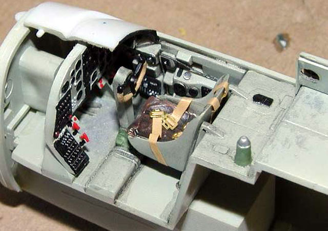
Internal
Internally the most effort was expended in
enhancing the kit detail. In the cockpit enhancement was provided by the
addition of seatbelts made using masking tape and finished with some PE
buckles. Wiring was added to the sidewalls and floor and the small
panels mounting fire extinguisher controls to the lower instrument
panel. A small hand held extinguisher was scratch built and added behind
the pilots seat.
As I wanted to display the canopy open
enhancement of the life raft bay was required. Sidewalls were drilled
and fashioned from sheet styrene. The inside of the hatch was enhanced
by drilling out the weight saving holes, adding a sun screen made out of
fine wire and tin foil, and scratch building some internal details and
latches. The bay was finished with the addition of a scratch built life
raft, in hindsight the available resin accessory would have looked
better.
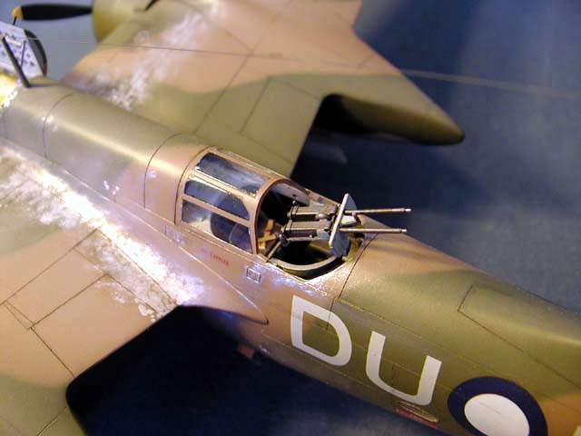
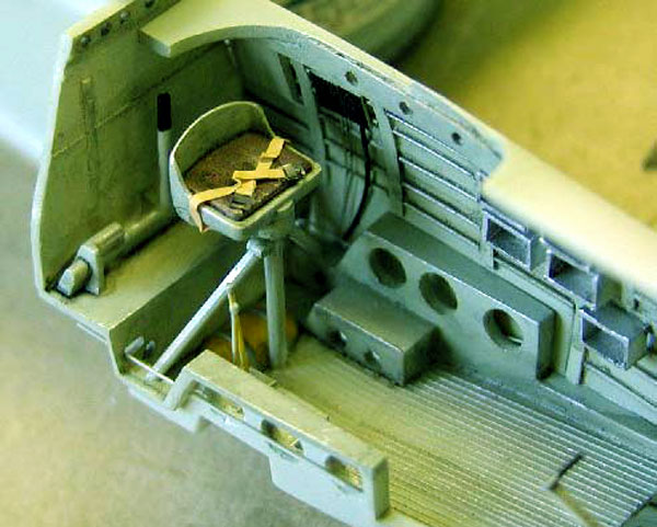
The
mid-upper crew position required a little more effort.
Internal ribbing was scratch built along with racks for ammunition
boxes. Visible cabling was added, as was controls for the opening of
lower hatches. Seatbelts for the crew station similar to the cockpit
were added and the barrels for the twin 30 Cal guns were replaced with
hypodermic tubing. Careful washing and dry brushing completed the
respective cockpits.
Fuselage and Nose Section
The fuselage was joined without incident
once some small guides were made for the bomb bay doors. At this point I
added the horizontal tail surfaces, vertical surfaces would follow
later. The hole at the rear of the fuselage was covered with styrene and
the clear tail light cover added. These were then sanded and polished to
an acceptable finish. Work now commenced on the nose section.
In this area lots of dry fitting saved my bacon. It was found that the
two piece lower nose was smaller than the fuselage width, but the glazed
section was the right size. My solution was to add a 2.5 mm spacer
between the lower sections and join these to the clear before fitting to
the fuselage.
No filler was required between nose and
fuselage but some sanding of the clear parts was required. This sanding
removed some of the raised detail on the clear parts, and as a result I
removed it all. The conversion to an 8-gun nose replaced plexiglass
panels with aluminium ones so preservation of a clear surface was not
required. The raised detail previously removed was replaced with very
fine masking tape and sealed with a clear varnish. Four holes were
drilled into the forward flat surface of the section and all 8 MG
barrels were replicated with hypodermic tubing.
Work now commenced upon the wings and tail.
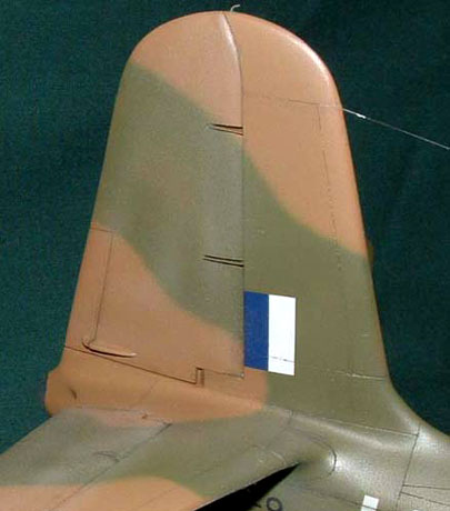
Wings and Tail
To make the vertical tail surface accurate
a little effort is required. Firstly the two kit rudder mounts were
hollowed out with a scribe. Two small triangular pieces of styrene were
then added to replicate the flat rudder mounts. A scratch built two
piece housing for the rudder trim mechanism was then added to the lower
right side of the fin. The assembly was then placed on the kit and
substantial filing was completed to gain an acceptable join.
The wings were joined in the standard manner before fitting. In order to
get the right dihedral the kit comes with a form of main spar, but a
couple of mm need to be shaved off the botom at the ends in order to get
the correct effect. This also helps in reducing the amount of filler and
sanding required for the wing to fuselage joint.
Engine Nacelles
The kit engine nacelles require fair amount
of work to firstly improve the accuracy and secondly, be converted to
DB-7B standard.
Work commenced on the inboard side oil
cooler intakes. The kit provides intakes and vents that open directly
into the undercarriage bay. Using sheets of styrene cut and bent to
shape along with some stretched sprue the required vertically divided
intake was created. A similar method was used to represent the exit
vent.
After significant dry fitting the outboard
side was cut and a mount for the single exhaust was built. Care should
be taken here that the mount does not protrude into the undercarriage
bay so much that it interferes with the upper legs. The two halves of
the nacelle were then joined.
There is a lot of scope here for further
detailing as the internal bay is very sparse. However from experience
with the G model any scratch built detail will not be easily seen,
accordingly I added no further detailing. The nacelles were then joined
to the wings, some small spacers in the locating recess helped to
achieve a join that did not require filler. Both nacelles were placed
over the already inserted upper undercarriage mounts, less the leg.
Undercarriage Accuracy
The kit undercarriage though basic is
reasonably accurate in all areas except for its placement. The locating
holes given mean that the legs are placed much to far to the rear. I
alleviated this problem by creating new ones 4mm forward. This was not
quite enough and if I were to build another, a 6 mm move would be used.
Engines and Cowlings
The kit engines are quite basic, but have
scope for improvement. The only improvements I made was to add ignition
leads. This was done by painstakingly drilling mounting holes for all
leads and then threading monofilament through. Small clips to hold the
leads together were made from styrene before careful painting, washing
and drybrushing was completed to produce an acceptable finish.
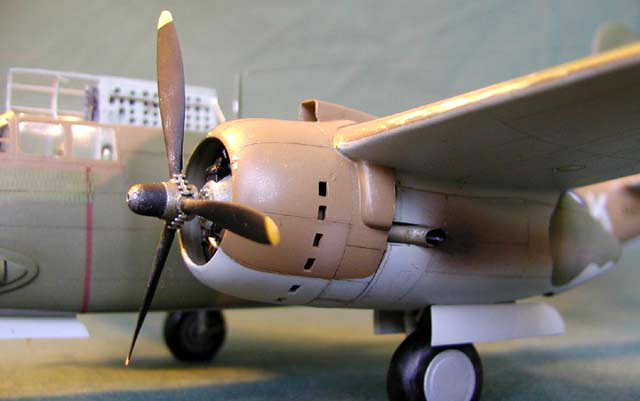
The fixed vents were produced by marking the holes out with pencil,
before drilling and squaring off with a fine hobby blade. The inside of
the cowl was then thinned down with a motor tool. I had some designs to
replace the scribed cowl flaps with some scratch built ones but baulked
at the effort required to scratch build the visible detail at the rear
of the engines. Accordingly the flaps remained in the closed position.
Finally the single exhaust was fashioned from brass tubing, with the
opening suitably thinned to scale.
The remainder of the kit was built as per
usual with the addition of replacing the nose gear doors with ones that
were of scale thickness and opening the boarding ladder hatch. A scratch
built ladder was also added in its deployed position.
The kit wheels were used albite with the
weird fish scale tread removed, these remained attached without glue so
true details resin ones can be added in the future. HF antennae and
fixed forward sight were made from monofilament.
Painting,
Markings and Weathering
|
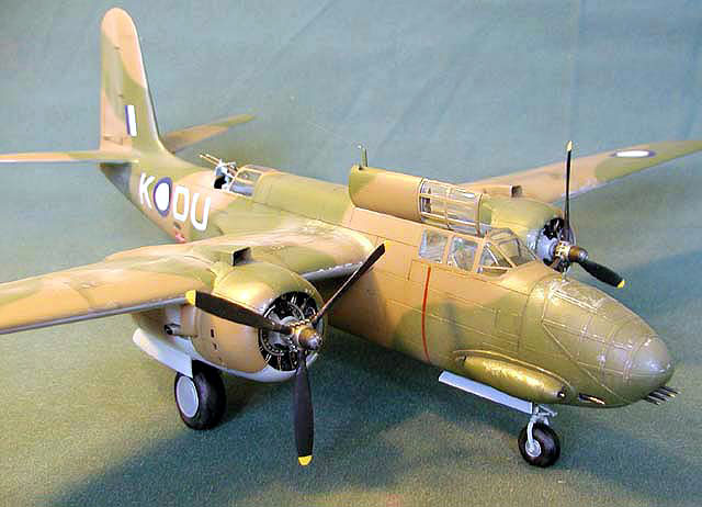
 22 Sqn Bostons were finished in the
standard RAF Dark Green Dark Earth and sky type S finish. This was
replicated with Humbrol, Model Master and Aeromaster enamel paints. The
kit was given a coat of Future before decaling and weathering. Decals
are from the Aussie Decals range. The aircraft depicted is DB-7B/Boston
III A28-9 DU-K as it was seen in early 1943. 22 Sqn Bostons were finished in the
standard RAF Dark Green Dark Earth and sky type S finish. This was
replicated with Humbrol, Model Master and Aeromaster enamel paints. The
kit was given a coat of Future before decaling and weathering. Decals
are from the Aussie Decals range. The aircraft depicted is DB-7B/Boston
III A28-9 DU-K as it was seen in early 1943.
Weathering was achieved by dry brushing Model Master Aluminium buffing
Metalizer, and adding washes of dark green, black, grey and raw
umber. Finally a flat coat from the Floquil railway colors range was
used.
-
Wilson, S. 1992, Boston, Mitchell and
Liberator in Australian Service, Aerospace publications Pty Ltd, Weston
Creek ACT
-
Flightpath Magazine Vol 10 No 1. pp. 66-75
article on the RAAF Museums Boston III restoration.
Click on the thumbnails
below to view larger images:
Model, Images and Text Copyright © 2002 by
J.D. King
Page Created 10 July, 2002
Last Updated 04 June, 2007
Back to HyperScale
Main Page
Back to
Features Index
|
 Home
| What's New |
Features |
Gallery |
Reviews |
Reference |
Forum |
Search
Home
| What's New |
Features |
Gallery |
Reviews |
Reference |
Forum |
Search