|
Messerschmitt Bf 108
by Brett
Green
|
 |
|
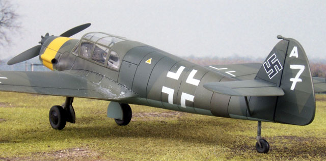
Messerschmitt Bf 108D
Unknown Unit, Neubiberg, May 1945
(typical colours and markings) |

Eduard's 1/48 scale Messerschmitt Bf
108B-2 is available online at
Squadron
The Messerschmitt Bf 108 was initially designed as a sports aircraft
in 1934. The definitive four-seater version was the Bf 108B.
The Bf 108 had advanced features including an all-metal airframe,
automatic leading edge slats, adjustable propeller and retracting
undercarriage. The Luftwaffe adopted this aircraft in the communication
and liaison role. An improved version, the Bf 108D, was introduced in
1941 and began rolling off French assembly lines from 1942 until the
liberation of France.
The Messerschmitt Bf 108 was a popular aircraft in wartime due to its
comfortable leather seats and pleasant flying characteristics. These
same features also ensured that the Bf 108 retained its popularity in the
post-war civil aviation market.
Eduard's 1/48
Scale Messerschmitt Bf 108B-2
|
Eduard has diversified their usual First World War focus
with two WWII releases in the last few years. The first was the Bell P-39
Airacobra family, and the latest is the Messerschmitt Bf 108. Although the
P-39s and Bf 108 were not the first WWII aircraft kits offered by Eduard,
they are the first to have benefited from their recent long-run,
metal mould technology.
Eduard's 1/48 scale Messerschmitt Bf 108B-2 comprises 87
parts in khaki coloured styrene; two parts in clear injected styrene; one
paper sheet of instruments and decals for two aircraft. Masks for the
glasshouse canopy are also included.
The plastic parts are first rate in every respect. For a
more detailed examination of the kit in the box,
check my
recent review elsewhere on HyperScale.
 Eduard's 1/48 scale Messerschmitt Bf 108 was generally a
straightforward model to build, but there were a few challenges as
described in the text below. Eduard's 1/48 scale Messerschmitt Bf 108 was generally a
straightforward model to build, but there were a few challenges as
described in the text below.
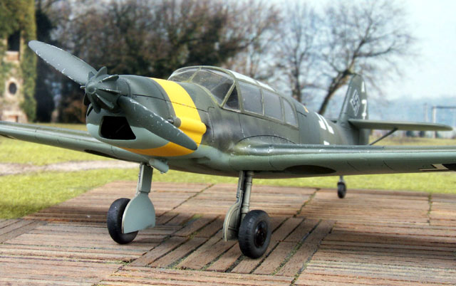
The kit parts include an alternative boss and spinner for the Argus
automatic adjustable propeller. Although the instructions do not mention
these parts, they can be used to depict the later Bf 108D variant. I
decided to use these parts to build a late-war liaison aircraft
operating in southern Germany.
I built the model straight from the box with the only enhancements
being brass harnesses for the front seats and decals from the spares
box.
Step 1 - Cockpit
The kit cockpit is made up of 24 parts. Although the one-piece kit
canopy is fixed shut, all the glorious detail in the cabin can be seen quite
clearly through the big, glasshouse windows. I added lap harnesses
to the front seat from the True Details brass set for Hasegawa's 1/48
scale Stuka.
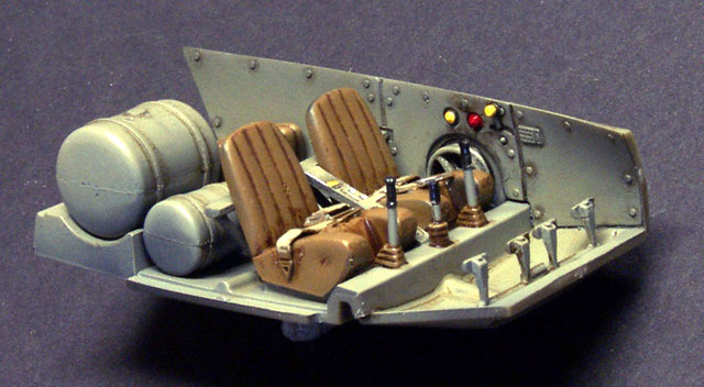
Auxiliary fuel drums are supplied as an option for the back
seat. I decided to use this option.
Two instrument panels are supplied. One is solid plastic, designed
for painting or for applying a decal. The second has holes to reveal the
instruments. The instruments are printed onto a small piece of paper.
These are simply glued to the back of the plastic part to create an
effective, three-dimensional instrument panel. I added a drop of
"Future" floor wax to each instrument to represent the dial lenses.
The prominence of the cockpit makes a careful paintjob worthwhile. I
sprayed the main components with Gunze H70 RLM 02, then painted the
"leather" seats using Gunze H72 Dark Earth. When dry, the main cabin
received a black oil wash, and the seats were washed with a thinned mix of
Burnt Sienna and Raw Umber oil paints. Details were then picked out using
Tamiya Acrylics. Click the
thumbnails below to view larger images:
|
|

|
|
Lap harnesses were added to the front seats from a True Details brass etched detail set
|
|

|
|
Cockpit components were painted before assembly
|
|

|
|
The seams on the fuel drums are invisible once they are trapped between the cockpit sidewalls.
|
|

|
|
The completed instrument panel. The oil wash has not yet dried. Future floor wax has been carefully applied to the instrument lenses.
|
|
|
Step 2 - Engine
Eduard's tiny Bf 108 engine is as well detailed as the cockpit.
I was initially concerned that none of the engine would be visible
behind the closed cowl. However, much of the cylinder, exhaust and
crankcase detail may be seen through the large front intake and lower rear
vent.
I assembled the firewall/mounts and the engine as separate
sub-assemblies to simplify painting. The only problem I found was that the
lengths of the rods (parts C16) could vary depending on where
the parts were cut from the sprue. The demarcation for removal was not
entirely clear. They are also quite fragile and easy to lose.
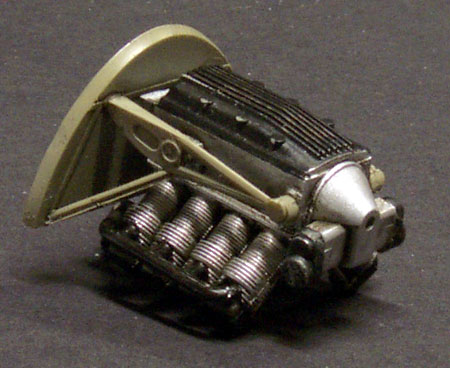
The firewall and mounts were sprayed RLM 02, and the engine received a
coat of Testors Aluminium Metalizer. Details on the engine were picked out
in Tamiya X-18 Semi-Gloss Black and the exhaust extractors painted Testors
Burnt Metal Metalizer before all the components were washed in a thin mix
of Black and Raw Umber oil paint.
The painted sub-assemblies were glued together after the paint had
dried.
Click the thumbnails below
to view larger images:
|
|

|
|
The completed firewall/mount and engine sub-assemblies.
|
|

|
|
Painting is underway. The components have received their base colour and the oil wash has commenced.
|
|
|
Steps 3 & 4 - Wing and
Fuselage Assembly
I had problems aligning the fuselage and the wing
assemblies. The problems were lessened after some serious sanding of
sidewalls and trimming of kit parts, but gaps still resulted even after
the modifications.
Click the thumbnails below
to view larger images:
|
|

|
|
Both sidewalls needed significant thinning and reshaping to permit the fuselage to fit properly at the wing root.
|
|

|
|
Even after the modifications, there were noticeable gaps on both sides of the trailing edge of the wing root...
|
|

|
|
...the port side upper wing root...
|
|

|
|
...and the starboard side upper wing root. The wing roots of the upper wings had been trimmed too.
|
|

|
|
A small gap was present on the upper surface of the starboard horizontal stabiliser.
|
|
|
I
would suggest the following assembly sequence to avoid these problems:
-
Assemble the
trim wheel and add it to the port sidewall.
-
Add the back
seat backrest (part A16) to the rear cockpit bulkhead (part A4), and
glue this to the rear of the cockpit floor (part A3). Do not glue
the sidewalls to the floor yet.
-
Glue the wing
upper halves (parts B2 and B3) to the lower wing (part B1). Take extreme
care not to get excess glue in the locating holes for the undercarriage
legs. Set aside to dry. Do not cement the cockpit tub to the
floor of the wing yet!
-
Carefully
trap the engine firewall between the fuselage halves. When satisfied
with the fit, apply glue to the edges of the firewall and join the
engine cowl halves. There will be quite a bit of flex in the fuselage,
so glue and tape the engine cowl securely before gluing the back of the fuselage
halves. Locating pins are scarce, so make there are no ridges or gaps at
the long join lines. Set this assembly aside to dry.
-
Scribe an
oval filler cap on the top of the port-side fuselage at this stage.
Eduard has omitted this detail (which only became obvious to me when I
applied the filler stencil decal under a featureless expanse of
plastic).
-
When the
fuselage and wings are thoroughly set, test fit without the
cockpit in place. Now test fit with the cockpit floor locked over
the raised undercarriage well. Finally, test fit with the sidewalls
tacked in place using Blu-Tack, or simply resting against the cockpit
bulkheads.
-
If fit
problems are experienced during any stage of the test fitting, I suggest
the following remedies:
-
Enlarge the
gaps under the cockpit floor that sit over the top of the gear leg
bays. Add one or two millimetres to the front of this space using a
sharp hobby knife. This will permit the cockpit tub to slide back
slightly.
-
Thin the
sidewalls. It may also be necessary to slightly shorten the
height of one or both of the sidewalls.
-
As a last
resort, sand the wingroot of the upper wings to minimise any gaps.
-
Glue the
assemblies, set aside to dry. Fill and sand as required.
-
Add the tail
surfaces.
Steps 5, 6 & 7 - Finishing
A gap-free join between the large
canopy and the fuselage is essential for a realistic Bf 108. I decided to
tackle this area before adding the finishing touches.
First, I test fitted the canopy
to the fuselage. The canopy seemed slightly too long, so I sanded the flat
rear mating surface on the upper fuselage. This resulted in a tight fit,
but now the profile of the lower front right corner of the canopy did not
match the contour of the fuselage in the same area. I carefully rounded
the corner of the canopy with a medium grade sanding stick. The fit was
now perfect.
I added the instrument panel and
coaming (parts C24 and C25) to the top of the interior sidewalls and slid
the coaming slightly under the top of the cowling. I test fitted the
canopy again to ensure that the coaming did not foul against the canopy.
With the canopy tightly wedged in place, I ran a line of liquid glue along
the joins, being careful to avoid getting any excess glue on the clear
part.
As a result of my earlier
misadventures, I had to fill and sand a number of gaps around the wingroot.
I also had to eliminate a step between the fuselage halves on the upper
fuselage join.
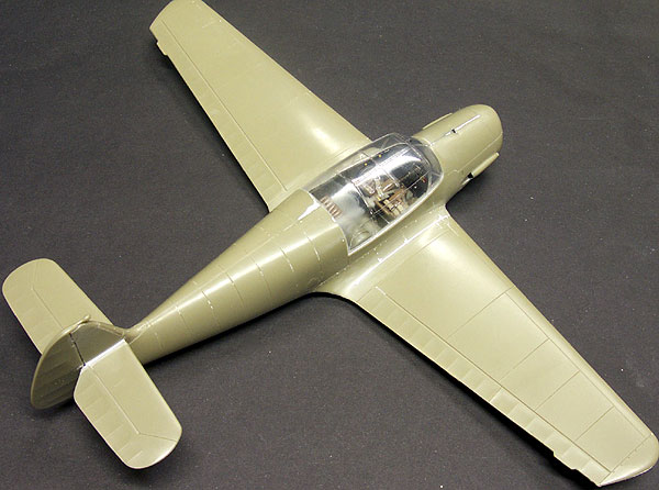
I have heard that some HyperScale
visitors use Liquid Paper as a filler for fine gaps. I decided to try
this technique for the first time myself. I applied Liquid Paper to gaps,
steps and seams using the brush supplied in the bottle. After a few
minutes, I sanded the filler with dry 400 grit Tamiya abrasive paper,
followed by finer grades and finally polishing the plastic surface with
"Mr Rubbing Compound" and a soft cloth. Polishing the model ensures that
all the scratches, gaps steps have been eliminated.
Although Liquid Paper would not
be suitable for larger gaps, I was quite happy with the results.
Click the thumbnails below
to view larger images:
|
|

|
|
Liquid Paper was used to fill the narrow gaps, seams and steps.
|
|

|
|
The clear portions were masked to avoid accidental damage. The filler was sanded with Tamiya Abrasive Paper.
|
|

|
|
When sanding was completed, the model was polished with "Mr Rubbing Compound" and a soft cloth.
|
|

|
|
Dymo tape was then used to restore panel lines lost during sanding.
|
|
|
I confess that I don't normally like painting RLM 70/71
splinter camouflage. However, I decided to take up the challenge of trying
to make this sometimes dull finish look interesting.
I built my Bf 108 as a late-production "D" variant. It
does not represent any particular aircraft, but the paint job is based
upon markings observed on liaison and communication aircraft abandoned in
the Luftwaffe's southern operational sector late in the war.
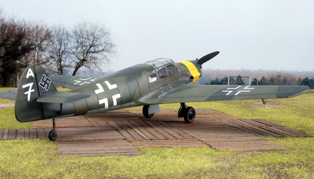
The yellow cowl band was a theatre marking, and the
hand-painted number on the rudder was a tactical identification. Some
liaison aircraft also sported a small letter above the number.
Masking
Eduard supply a set of Express Masks for the large framed canopy. This made
quick work of the biggest masking task. I
supplemented the masks with Tamiya tape to cover the larger spaces.
Earlier experience with Eduard masks made me cautious - paint has leaked
under this brand of mask on other models. I therefore burnished the edges
of the masks with a sharpened wooden stick to seal them properly.
The cowl intake, lower vent and wheel wells were stuffed
with tissue paper to prevent overspray.
Yellow was sprayed on the nose of the aircraft, and RLM 81
Brown-Violet was painted on the rear fuselage. This patch of RLM 81 depicted an oversprayed yellow fuselage band. The fuselage band
was sometimes removed when the yellow cowl band was added. Both bands were
masked with Tamiya tape.
Click the thumbnails below
to view larger images:
|
|

|
|
Eduard Express Masks are in place. The gaps have been covered with Tamiya masking tape, cut to size.
|
|

|
|
The wheel wells, cowl intake and vent have been stuffed with tissue paper. The wheel wells have already been painted RLM 02.
|
|

|
|
The canopy has been sprayed RLM 02 (the colour of the framing). The nose and fuselage bands have also been painted.
|
|

|
|
The nose and fuselage bands are masked. The model is ready for its camouflage!
|
|
|
Painting
I dispensed with my usual pre-shading on this model. The
pre-shaded lines would be almost invisible underneath the dark upper
surfaces, so I loaded my Testors Aztek airbrush with Gunze RLM 02 for the canopy framing.
This coat also served as a final check for any remaining gaps and
scratches.
 The lower surfaces were sprayed RLM 65 Light Blue, then
the demarcation lines were masked with Tamiya tape. The lower surfaces were sprayed RLM 65 Light Blue, then
the demarcation lines were masked with Tamiya tape.
I felt that the Gunze RLM 71 looked too dark, so I
lightened it slightly with Gunze H303 Green FS34102. When the base coat of
RLM 71 was dry, the camouflage pattern was masked using a combination of
Post It Notes and Tamiya masking tape. Gunze RLM 70 Black Green was also
lightened until the contrast between the two colours looked right.
Although there is no doubt that German RLM 70/71 splinter
camouflage is hard-edged, I think that the finish can sometimes look too
stark on a model. I tried to address this problem without resulting in a
soft-sprayed effect.
The darker green was sprayed lightly up to the edge of the
mask. The mask was then removed and RLM 70 was resprayed along the
hard-edged line. This marginally softens the demarcation to represent a
slightly weathered splinter camouflage.
With the painting completed, the masks were removed. The
paint was buffed with a soft cloth and the glossy surface was ready for
decals.
Markings
The only kit decals used were for the lower wing. The
registration was slightly off, but there was virtually no excess carrier
film and the decals settled down beautifully into panel lines. I took the
outline-style national markings and fuel triangle from an EagleCals sheet
for the Focke-Wulf Fw 190.
The rudder markings were hand-painted onto clear decal
film. I used Tamiya Flat White paint for this job.
Earlier in this article I urged caution to avoid getting
excess glue in the holes for the main gear legs. I did get glue into one
of these locating holes, and it caused me an unwelcome diversion when the
model was close to completion.
I added the various finishing touches to the kit including
pitot tube, aileron mass balances and the landing light. I also assembled
and painted the main gear legs. These feature a decent locating pin to
insert in the lower wing. However, the locating hole for one of the legs
was full of hard, dried glue that must have spilled over from the fuselage
join. Unfortunately, the locating pin was semi-circular in profile, so I
couldn't simply drill out the hole without weakening the join.
I decided on brute force instead.
You know this stage of construction. You can see the light
at the end of the tunnel. The finished model is so close that you can
taste it. So you take a short-cut.
As I was fruitlessly pushing the leg into the blocked hole
I heard a "crack". The exertion had split the starboard wing root join.
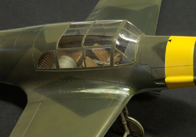
My short-cut turned into the scenic route as I was forced
to sand back the wing root, re-spray the area, polish and match the
surrounding paint and then drill out the gear leg locating hole
anyway!
Weathering
I applied a thin wash of black oil paint to the panel
lines. The canopy was masked again and the entire model received a
thin coat of Gunze Flat Clear.
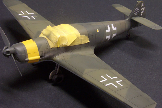
Weathering was kept to a minimum with a
light exhaust stain on the fuselage side and lower surfaces and some
walkway chipping on each wing root using a silver pencil.
Despite the challenges presented by the kit and by my own
haste, I found Eduard's 1/48 scale Messerschmitt Bf 108 to be a quick and
enjoyable project. The comprehensive engine and cabin detail, straight
from the box, is very impressive for a plastic kit in this price range.
In the six days since the kit was delivered I have found
references of some attractive options for the Bf 108 operating under the
flags of Great Britain, the United States and, of course, France. It will
be interesting to see what company is first to market with alternate
decals!
|
Home
| What's New |
Features |
Gallery |
Reviews |
Reference |
Forum |
Search