|
Fuselage
Although I was not planning to install cameras in my model, I
still added the rear fuselage bulkhead (part B2) for reinforcement.
The instructions suggest the installation of the main landing
gear prior to the joining of the main fuselage halves. It would be very tricky
to install the landing gear legs once the fuselage halves were joined, even
though the suggested assembly sequence does complicate painting later. However,
I advise that the main gear doors (parts B14 and B15) should be left off until
the model has been painted. I painted the main gear bay and landing gear legs
RLM 02 and glued them in place.
The fuselage halves were joined without incident. However, the
fit of the clear inserts on the top and the bottom of the fuselage was less than
perfect, with steps between the clear parts and the grey plastic fuselage.
 At
this stage a large lead sinker was glued into the front of the main fuselage
section (click thumbnail at right to view larger image). This acted as a
noseweight to keep the model sitting on its nosewheel.. At
this stage a large lead sinker was glued into the front of the main fuselage
section (click thumbnail at right to view larger image). This acted as a
noseweight to keep the model sitting on its nosewheel..
Wings, Flaps and Nacelles
Cutting Edge has also released a set of separate flaps for
Hasegawa's Ar 234. I decided that these would add some character to my model, so
I prepared the kit parts.
The four resin parts are cast in Cutting Edge's customary
grey resin, and are separated into left (port) and right (starboad)
casting blocks with inner and outer flaps supplied. Casting quality is
first rate, and the parts are very easily removed from their casting
block. A little care will be required to avoid slicing off the small hinge
lugs when cleaning up the outer flaps.
Click the thumbnails below to view
larger images:
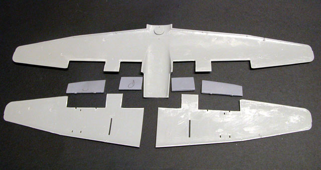
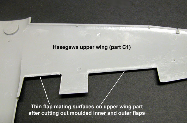
Preparing the kit wings for the resin flaps is not too difficult. I used a
scriber and a sharp hobby knife to remove the inner and outer flaps from
the top and bottom sections of the wings. I then proceeded to thin down
the plastic where the flaps will be glued to the top wing. A hobby knife
was scraped along this area until the edge was very thin.
The kit wing parts were joined, and the resulting gaps on
either side of each flap bay were filled with Milliput White Epoxy Putty
and sanded smooth.
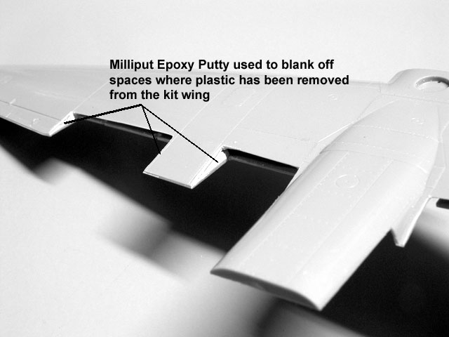
The resin flaps were not glued to the wings yet.
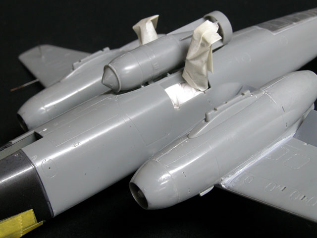
The engine nacelles were assembled. The fit of these parts
to the leading edge of the wing was not great. I spent a few minutes
sanding and trimming the nacelles before gluing the sub-assemblies to the
lower wings.
The fit of the wing to the fuselage was also initially
disappointing. The top fuselage join was particularly bad, displaying a
noticeable step. I trimmed and sanded the forward wing roots, which
reduced the height of the top fuselage join and mostly eliminated the
step.
It is essential to note that the forward bulkhead (part A18) is
slightly too big for its space in the forward fuselage. If this piece is glued
in place without modification, the nose section will not fit properly. I trimmed
the edges and bottom of this forward bulkhead, test-fitting against the nose and
fuselage parts until the fit was perfect. The part was then glued into place.
The horizontal tail surfaces were added now.
Mr Surfacer was brushed into a few of the small gaps and steps
before being sanded and polished. No further filler was required.
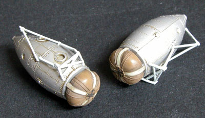
Finishing Touches
The only slightly tricky aspect of the remaining assembly is the
mounting structure for the rocket-assist pods. The angles have to be perfectly
aligned in order for the mounts to fit into the slots in the lower wings. It is
important to check the fit of the mounts against the slots while the glue is
still pliable.
The remainder of the kit was finished according to the
instructions with the following exceptions:
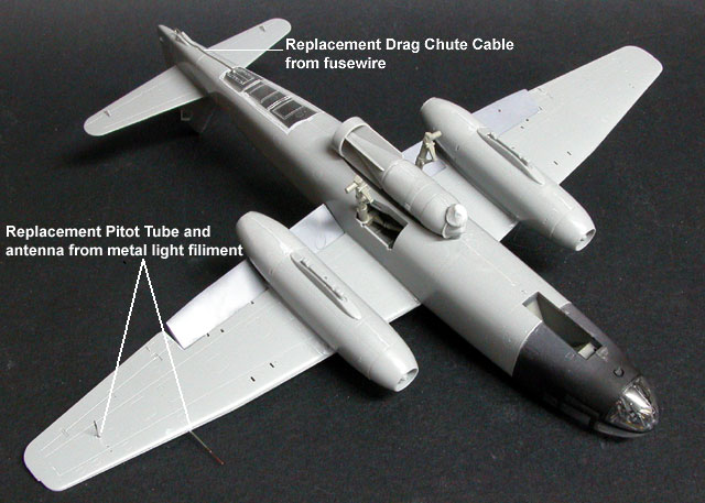
-
pitot tube was replaced with light
filament
-
lower wing antenna replaced with
light filament
-
drag chute cable replaced with
fusewire after plastic part broke on the sprue
-
resin Cutting Edge flaps added
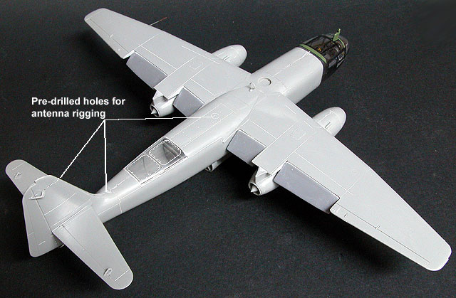
-
holes pre-drilled for antenna wires
-
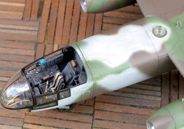
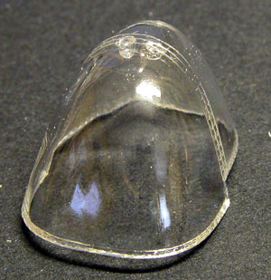
top clear canopy section not glued
in place. The fit was quite good without glue, so I have left it loose to
permit a better view of cockpit detail.
Bomber Colours - Old or New?
The official painting orders for Luftwaffe bombers in late 1944
specified the use of the new colours 81, 82 and 76.
However, it is well known that large stocks of the older bomber
colours, 70, 71 and 65, still existed and were widely used on various German
planes. It is very probable that the Arado Ar 234 wore a hybrid combination of
these colours. In most photos the contrast between the upper surface colours is
very low and the overall effect is usually quite dark.
In my opinion, a significant number of Ar 234s probably wore one
or both of the older green bomber colours.
However, for this project I thought the combination of 81 Brown
Violet and 82 Bright Green just looked too good to pass up!
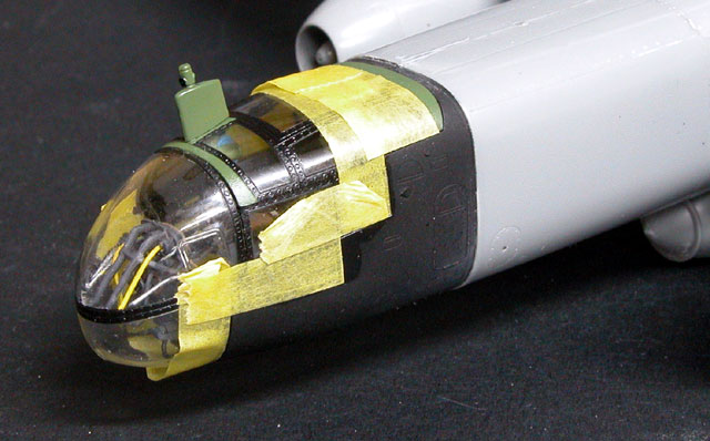
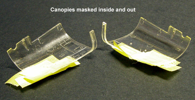
Masking
 The
first task before painting was masking the canopy. I used the new Black Magic
masking set (stock number CEBM48524) which includes masks for the camera windows
and night fighter windows too, if required. This masking set fitted the kit
parts perfectly and saved a lot of time and effort. The
first task before painting was masking the canopy. I used the new Black Magic
masking set (stock number CEBM48524) which includes masks for the camera windows
and night fighter windows too, if required. This masking set fitted the kit
parts perfectly and saved a lot of time and effort.
I did reduce the tackiness of the masks by pressing them against
my forehead before sticking them on the canopy parts. Those of you with less
acreage of forehead might consider using the palm of your hand.
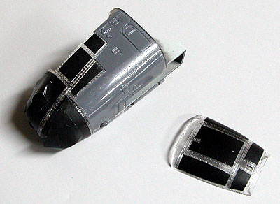
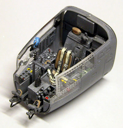
As discussed earlier, I used gloss black to suggest the frames
behind plexiglass. If I were to build this model again, I would spray the
framing before assembling the cockpit and dip the painted clear canopy parts in
Future.
The masks worked perfectly - no paint bleeding under the edges,
and no damage to the Futured clear parts on removal.
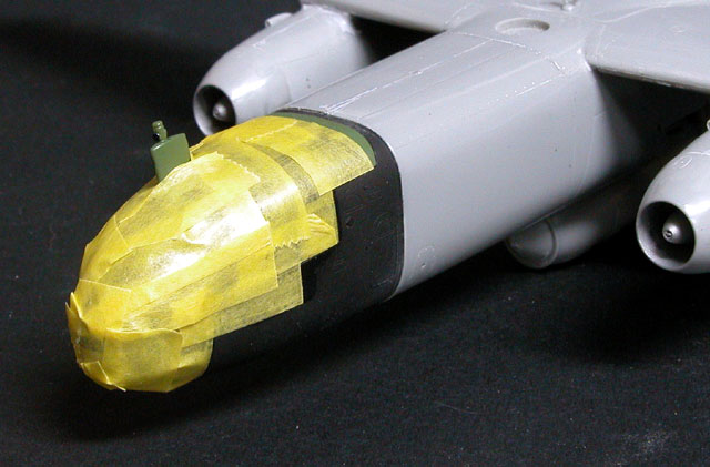
With the canopy frames painted, it was time to mask the entire
canopy area and undercarriage so that the camouflage could be painted.
Click the thumbnails below to view
larger images:
Painting
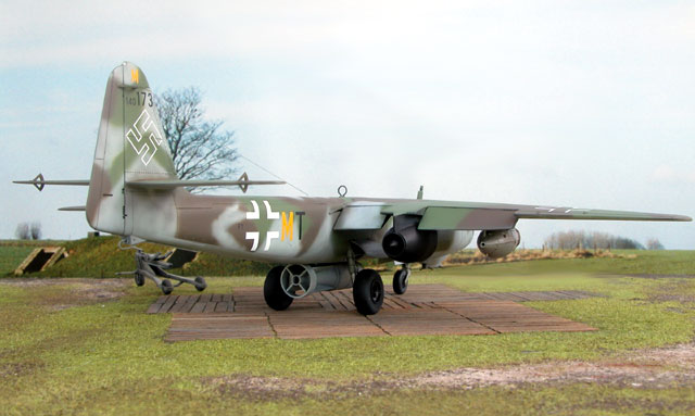
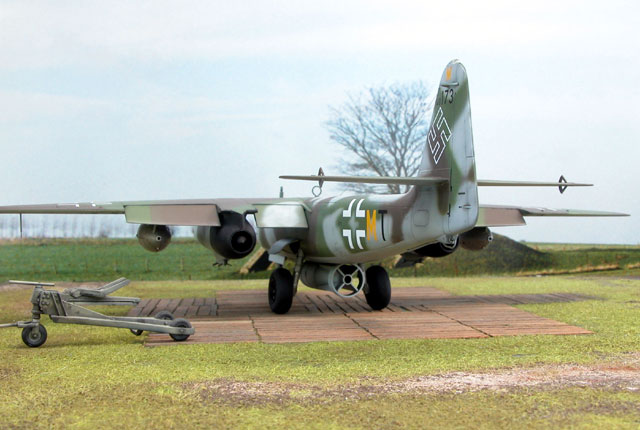
I wanted to paint a model with a soft overspray of RLM 76 Light
Blue. I also wanted the big 1,000 KG "Hermann" bomb and the Walter
bottles installed. This meant an operational machine and instantly reduced my
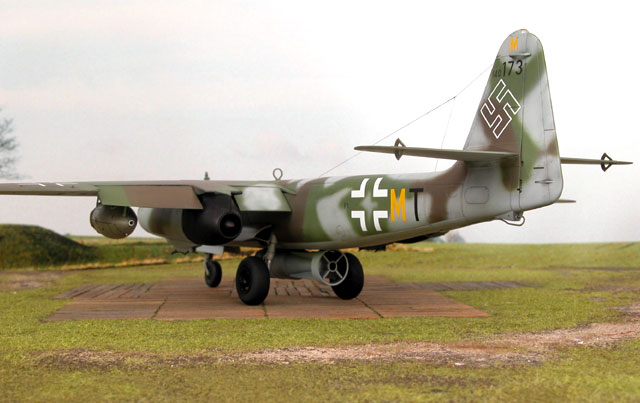
options. Cutting Edge's new decal sheet CED48201 included markings for W.nr.
140173, F1+MT. This machine fitted all of my requirements.
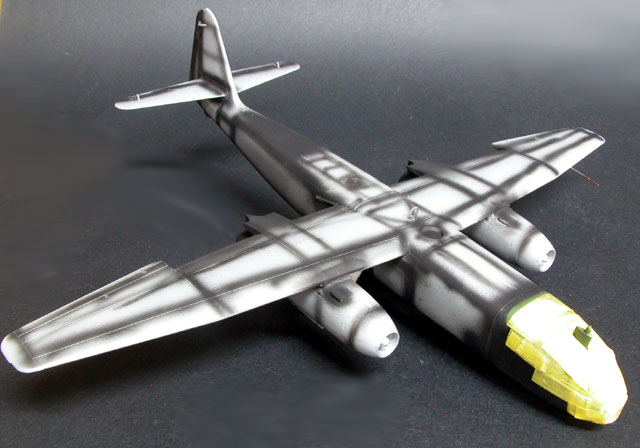
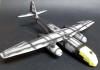
The panel lines of the Arado were "pre-shaded" with black paint
before a coat of Polly Scale RLM 76 Light Blue was applied to the lower
surfaces.
Click the thumbnails below to view
larger images:
|
|
|
|
Panel lines have been "pre-shaded" with black paint
|
|
|
|
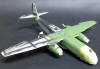
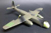
The first coat of RLM 82 Bright Green is underway
|
|
|
|
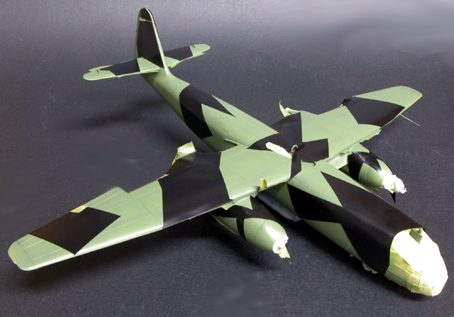
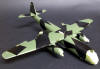
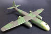
Following the Green coat, Black Magic masks are applied
|
|
|
|
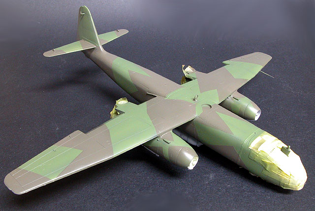
...and oversprayed with RLM 81 Brown Violet
|
|
|
|
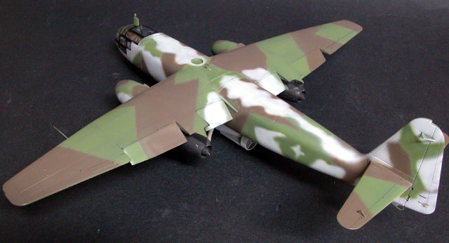
The camouflage masks are removed to reveal the final pattern
|
|
|
RLM 82 Bright Green was sprayed on the upper surfaces and
allowed to dry for a few hours before the Black Magic camouflage masks were
applied. Once again, these masks cut down on the time required to mask the
camouflage pattern, and was more accurate than I might have managed with
home-made masks or freehand spraying.
The camouflage on these Arados had quite a sharp demarcation
line, so I sprayed up close to the masks with RLM 81 Brown Violet. I thought the
colour looked a little pale. I therefore concocted a slightly darker mix,
removed the masks and overpainted the original colour.
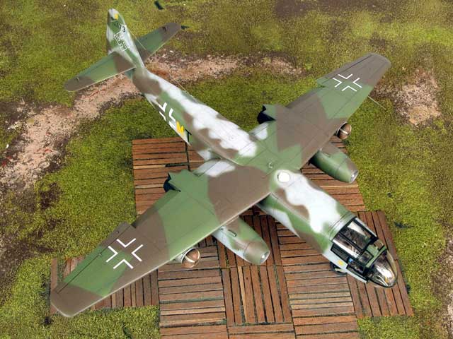
The RLM 76 Light Blue was sprayed freehand using the Testor
Aztek airbrush. The side overspray patterns were painted with the benefit of
reference photos, but the top fuselage pattern is based on my assumptions alone.
Details such as the wheels, rocket-assist bottles and the
episcope were painted prior to the application of decals.
Decals and Completion
I sprayed the fuselage sides and upper wings with Polly Scale
Gloss before adding the decals.
The Cutting Edge markings were completely trouble free. The size
of each decal looked accurate, and they instantly sucked down into panel lines
with the application of MicroSet.
After a few hours, a light acrylic wash was run into the panel
lines with a fine brush.
The front undercarriage, main wheels, main gear doors and rocket
pods were glued in place before a final coat of Polly Scale Flat.
The circular radio direction finder for the top of the fuselage
is a clear part with scribed detail to represent the fine array. I could not
decide how to paint this part, so I test-fitted it straight from the sprue. Much
to my surprise it looked terrific unpainted, so I secured it with a spot of
watchmakers' glue.
The very last task was to add smoke-coloured invisible mending
thread to the pre-drilled aerial wire holes. Super Glue was used to fix the
nylon thread.
Hasegawa's 1/48 scale Arado Ar 234B-2 is typical of recent their
offerings - generally accurate, well detailed and excellent surface features.
It is also typical due to the presence of a few irritating fit
problems - especially the wing and the forward fuselage bulkhead. These problems
are not especially difficult to overcome if the modeller is aware of them, but I
still find them irksome.
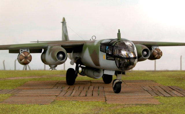
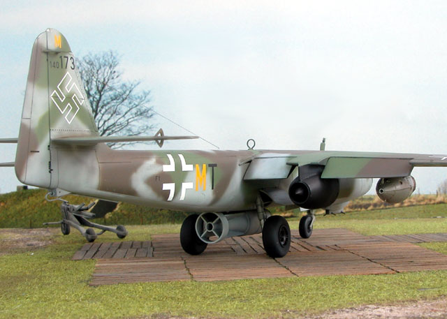
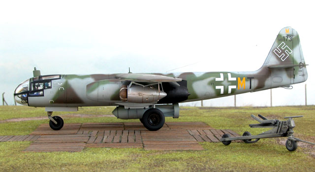
On balance though, this is by far the best Arado Ar 234
available in 1/48 scale, and quite possibly in any scale.
I am very pleased with the way my Blitz bomber has turned
out.
Click the thumbnails below to view
larger images:
Model, Images and
Article Copyright © 2002 by Brett Green
Page Created 23 October 2002
Last updated 04 June 2007
Back to HyperScale Main Page
Back to Features Page |
 Home
| What's New |
Features |
Gallery |
Reviews |
Reference |
Forum |
Search
Home
| What's New |
Features |
Gallery |
Reviews |
Reference |
Forum |
Search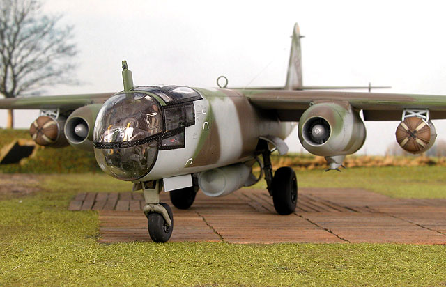

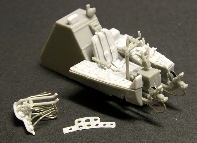
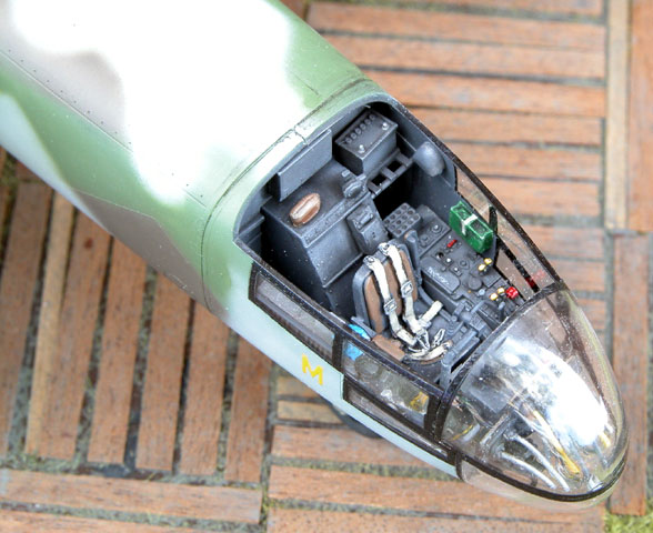
 The
painted cockpit sidewall details were added to the kit canopy frames. Extreme
caution must be used to avoid visible glue smears on the clear plastic parts
when gluing the regulator and flare pistol. I also added a short length of fuse
wire painted black to represent an oxygen hose attached to the regulator.
The
painted cockpit sidewall details were added to the kit canopy frames. Extreme
caution must be used to avoid visible glue smears on the clear plastic parts
when gluing the regulator and flare pistol. I also added a short length of fuse
wire painted black to represent an oxygen hose attached to the regulator.