|
How to Install
Seamless Suckers'
A-6E Intake
by Dave Roof
|
|
|
A-6E Intruder |

HyperScale is proudly supported by
Squadron
Seamless Suckers has been around for a few years
now.
Over the years Robert Brown, the ‘Head Sucker in
Charge’ has brought smiles to the faces of many Modern Jet Modelers. His
intakes have saved the modeler quite a few hours in one of the most
difficult areas of jet modeling, filling and sanding the seams inside
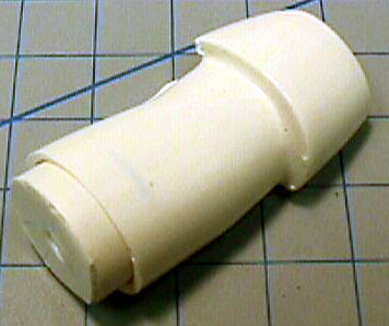
the intakes. The most recent release in this line is product number
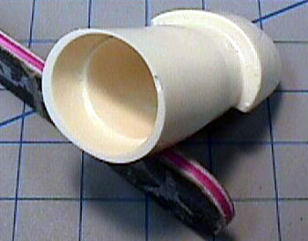
SS-24, A-6E intakes for the Revell 1/48 scale Intruder. The set consists
of four pieces in a hard white resin. The two intake’s, and the engine
faces for each.
On the real A-6E, the distance from the edge of the intake splitter
plate to the engine face is 7 feet. Revell’s measures out to a scale 2
feet. These new intakes are the correct 7 scale feet and give the kit a
much more realistic appearance.
Installation of the new intakes is pretty much straight forward.
However, like any resin aftermarket item, they may need to be modified
just a bit to fit your kit. Follow the directions, take your time, and
test fit often. It is recommended that you remove a little bit of
plastic from the kit at a time, dry fitting as you go.
 I have included a scan of the instructions for this review/build
article, so you can follow the steps (click
the thumbnail to the left to view larger image of the instructions). However, if you have a specific
question or the instructions are unclear to you, feel free to drop me an
email. I have included a scan of the instructions for this review/build
article, so you can follow the steps (click
the thumbnail to the left to view larger image of the instructions). However, if you have a specific
question or the instructions are unclear to you, feel free to drop me an
email.
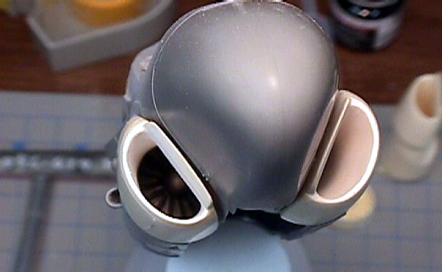
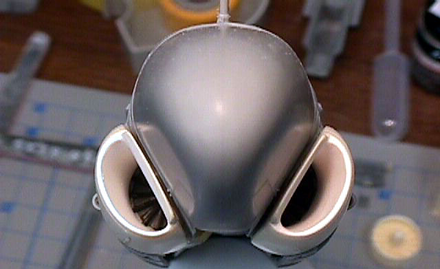
After removing the casting block from the backs of the intakes, wash the
parts in warm soapy water to remove the mold release agent. Once dry,
spray the interior of the intakes Gloss White and set aside to dry.
Next paint the engine faces Steel. When dry, insert
into the intake and push it in as far as it will go. It may be necessary
to remove a bit of the casting plug from the engine faces to prevent
them from hitting the main wheel wells in the kit.
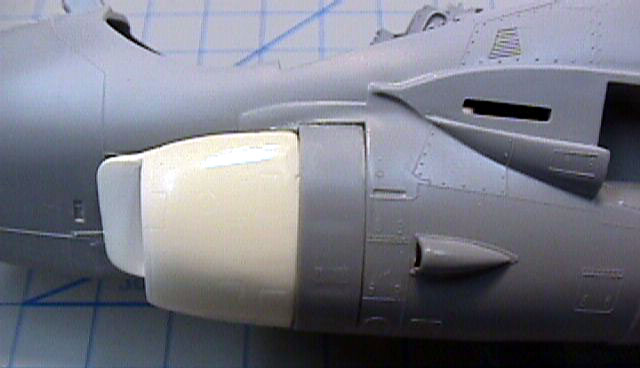
After removing the necessary plastic from the kit,
and you are satisfied with the intakes fit, glue the kit boarding ladder
door in the closed position on the left fuselage half. When gluing the
ladder door, you must first remove the detail from the inside, as this
will interfere with the intake itself. This will ensure you get the left
intake in the proper position.
Click the thumbnails below
to view larger images:
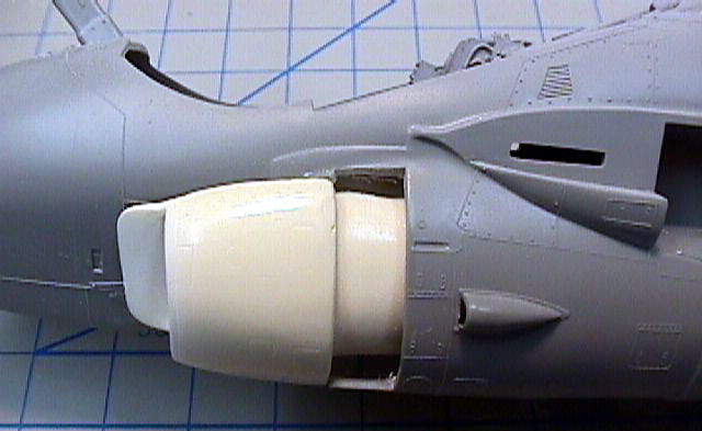
Now glue the intakes in position using either Super
Glue or 5 minute epoxy. On my kit, I tacked the boarding ladder door in
with white glue so I could remove it later.
Click the thumbnails below
to view larger images:
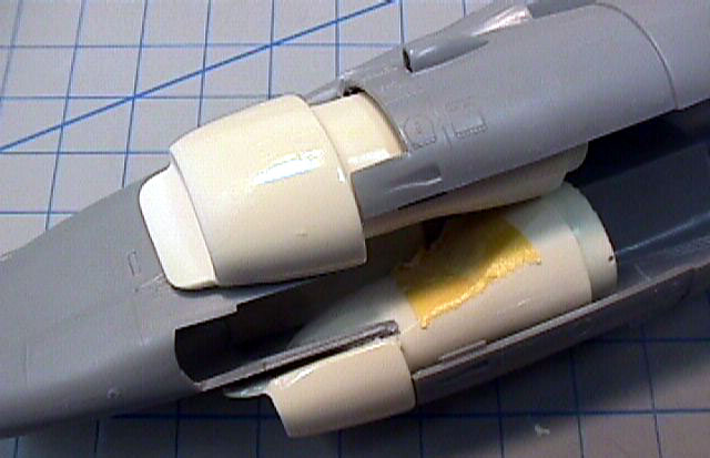
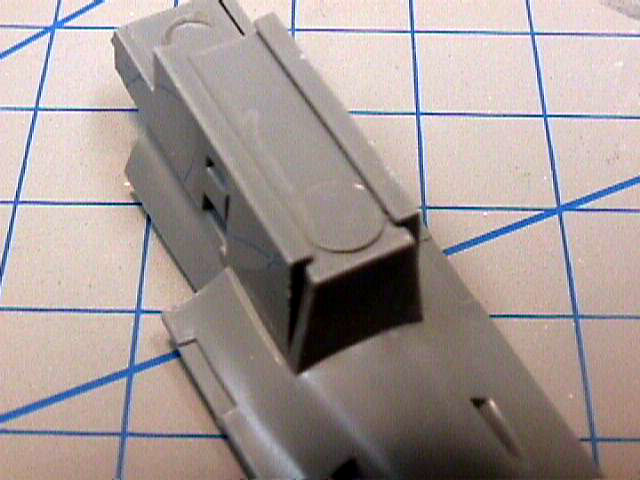
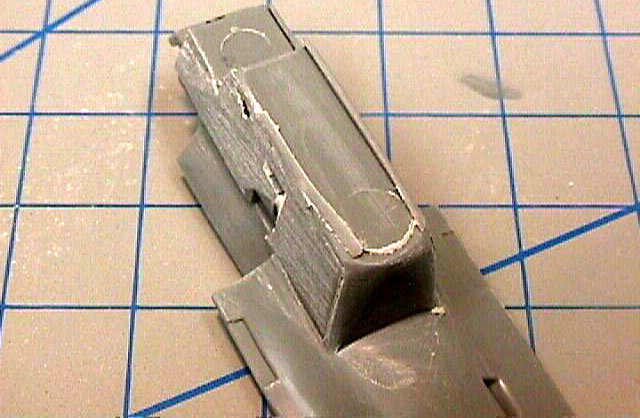
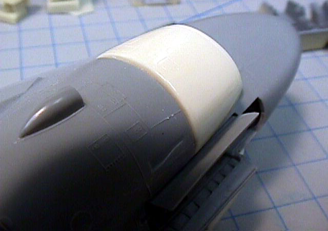
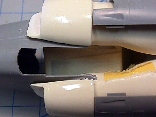
When you install the fuselage bottom and nose wheel well to the kit (kit
parts 11, 60, and 61), you will need to sand the wheel well as shown in
order for it to fit properly. You may also need to thin the intakes more
with a Dremel. You can see how the bottom fits without this
modification.
Click the thumbnails below
to view larger images:
The rest of the kit
will be built according to Revell’s instructions.
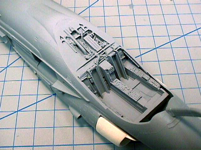
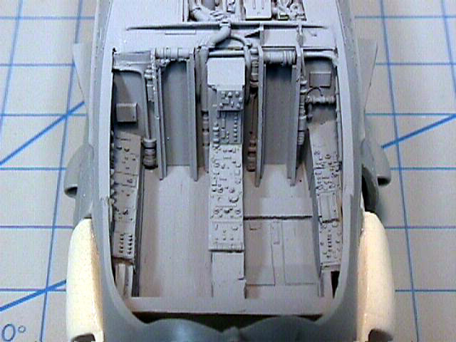
On my kit, I chose to add the Black Box cockpit and scratch build the
boarding ladder to show it in the down position. In order to get the BB
cockpit to fit, some surgery will need to be performed on both the
cockpit and the intakes. I had to thin the bottom of the cockpit tub so
much, you can almost see through it. I also had to thin the intakes
themselves to get the tub to seat properly. I can’t stress it enough.
Remove a LITTLE at a time and dry fit often until you get it right.
After a few dozens swipes with the Dremel, I was able to get everything
to fit snug.
Click the thumbnails below
to view larger images:
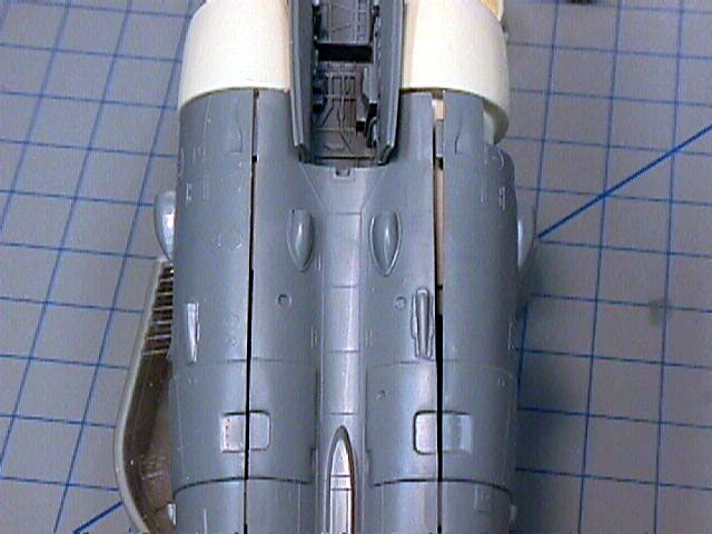
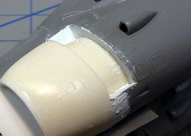
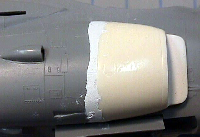
There was a slight step on the right intake to fuselage join, and a
small gap on the left intake to fuselage join on the bottom. I filled
both of these areas with White Miliput. I use Miliput because of it’s
working time, as well as the fact that it is easy to sand when dry and
sands to a glass smooth finish. You can also see where I used Miliput to
fill in the gaps where the boarding ladder will be. I used a sculpting
tool moistened with water to work the Miliput in.
Click the thumbnails below
to view larger images:
I hope you enjoyed this article. With any luck, I’ll have this
A-6E done in time for the North Central West Virginia Scale Modelers
show in November. I’ll try to get more photos posted when I finish.
Model, Images and Text Copyright © 2002 by
Dave Roof
Page Created 13 August, 2002
Last Updated 04 June, 2007
Back to HyperScale
Main Page
Back to Features Index
|
 Home
| What's New |
Features |
Gallery |
Reviews |
Reference |
Forum |
Search
Home
| What's New |
Features |
Gallery |
Reviews |
Reference |
Forum |
Search