|
Gekko Part Two
Completing Tamiya's
Nakajima J1N1Gekko (Irving)
"Straight Out Of The
Box"
by
Gregg Cooper
|
|
|
Nakajima
J1N1 Gekko (Irving) |

Tamiya's
1/48 scale Gekko is available online from Squadron.com
Tamiya’s Gekko kit is ideally suited to
building “out-of-the-box” (OOB).
In Part
One of this series I discussed some basic philosophies of OOB
modeling, and described the painting and detailing of the interior of
the kit. In Part Two, I will complete the interior, and move to the
exterior with some pointers on preparing the model for paint, and
improving some details while remaining within the boundaries of
out-of-the-box-modeling. Please
refer to
Part One for a review of the I.P.M.S. “out-of-the-box” rules and
discussion about “out-of-the-box” models.
My intention is to help modelers improve their
basic skills and mindset while providing proof that out of the box
modeling can be fun and produce a great model. These opinions are
my own, and reflect my years of experience, and what works for
me. I write this article with a mindset towards contest models,
but what I really intend to pass along is a way of thinking in terms
of quality. Also, I will go back to basics and discuss
some of the procedures that should become second nature in model
building. Basic construction is the cornerstone of a good model!
Building Tamiya's 1/48 Scale Gekko
|
Research
Researching a subject is one of my favorite
aspects of this hobby. My inspiration to build a model is a
combination of a love of history and the timely arrival of the latest
kit from the industry. Actually, I sometimes have a hard time
deciding if I am a modeler or a mini-historian because the two go hand
in-hand so well. Thanks to a painfully accumulated library, my
historical inspiration is usually well fueled, laying in wait for the
plastic model industry to catch up. Fortunately, Gekkos have been
well photographed, and WW2 close-ups that reveal good detail are
plentiful. I recommend Famous Airplanes Of The World (F.A.O.W.)
#57 and the 302 NFG special from Koku Fan for
authentic WW2 photos. There is also excellent coverage of the NASM
Gekko in the F.A.O.W. and in a new publication entitled
Modeler’s Eye #1 Gekko.
Completing the Interior
In these books I discovered an anomaly between
reality and the Tamiya kit. Somewhere along the line, Gekko
has been given an erroneous light perched in the clear nose cone of
the aircraft. Tamiya has included this light in their kit. A
searchlight? Landing light? The truth is, after looking at dozens of
good, clear photos, some from the inside looking out, I cannot
find a single photo of a light mounted in the nose of the aircraft.
It’s a shame too, because the light looks very nice in there. I
believe that the clear dome window was used to line up on targets for
the lower set of guns used on early versions of the aircraft. When
fitted, the lower guns were aimed through a second gun sight, mounted
in the middle of the instrument panel, aiming forward and down through
the flat window panels in the lower nose. An extra clear dome in the
tip of the nose would provide a little extra edge to keep things lined
up while maneuvering in the dark. When the lower guns were omitted
with later models, the clear dome remained, because it was still
useful to the pilot while landing.
I decided to build my Gekko without the light in
the nose. Tamiya’s kit features a separate nose cone that
incorporates the clear dome and light. There is a solid nose fitted
with radar arrays included with the kit that is meant for a future
release. Without the light, it is very easy to see inside the model’s
nose area. This is great for showing the detail of the air bottles
and tanks in the nose, but it also shows the ejector pin marks and
construction flaws more easily, especially so because the interior of
the nose is bare aluminum. After painting the interior parts, it was
time to test fit them into the proper locations. Not shown in the
first part of this article were the radio set and the air bottles in
the nose. In these photos you can see them installed into their proper
places.
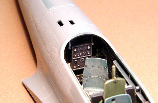
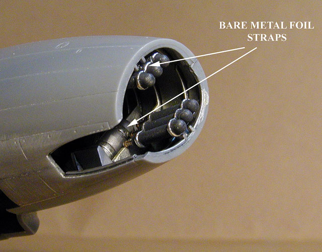
I used Bare Metal Foil “Chrome” to
simulate the retaining straps on the bottles and tanks. On the real
aircraft these were black steel bands, but I decided they needed some
extra punch to make them visible inside the nose compartment. I also
decided to close the armament hatch just to be different, so the
cannons were installed without the barrels in place.
Assembly Techniques
Before assembling any major parts, I always
dry-fit them first. I look for major fit problems, panel alignments
that may be a problem later, and make sure that the internal
components fit properly without interfering with the fit of the
fuselage halves. The next thing to do is prepare the mating
surfaces. In order to make a really good join, the mating surfaces
must be honed flat so that there will be no unforeseen gaps. Even
Tamiya cannot overcome the limitations of the molding process, and the
mating surfaces will not be perfectly flat. I use a variation of an
automotive painters trick called color sanding. Color sanding
is gradually removing layers of different color, such as black primer
over gray, until the surface is a uniform color. The odd colors stay
in valleys, and are removed from peaks, revealing where more attention
is needed. Fill or sand as needed. My variation is to use a pencil
on the edges of the mating surface. I use a six-inch flat file with a
“single cut” (sometimes referred to as a mill file) to work the
mating surfaces. I use the file laying flat across the fuselage and
resting on both edges of the part.
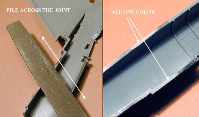
By working both edges at the same time, the file
is supported all the way across the cut, ensuring that the area
remains level and that both sides are even. When the pencil marks
disappear across both edges, the mating surfaces are ready. I use
this technique for any parts that are engineered in “halves”.
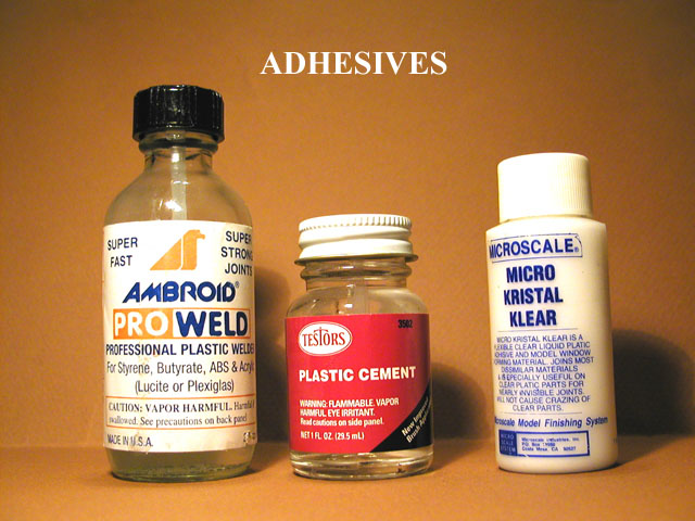
There are about as many different techniques for
assembling models as there are adhesives. I have tried just about
every available adhesive in American hobby shops over the past twenty
years, and many that aren’t. I have switched from this brand to that,
and varied my assembly techniques, but I keep going back to the way I
was taught many years ago. In order to get a good solid join, one
that I can count on for strength, liquid solvent is my choice. The
solvent melts the plastic parts together, and then evaporates away,
leaving a “welded” join. Other popular options are tube glue and CA
adhesives, sometimes called “super” glue.
I do not trust CA adhesives for joining major
assemblies, especially halves, because I have experienced
problems with them. I have had joined parts suddenly “POP” open. I
have had adhesive refuse to set up. I have had adhesive turn brittle
and fragile with age, leaving a model to virtually crumble apart. CA
adhesive has great tensile strength (pulling) but bad shear
strength (sideways movement). One good rap and the joint can
shatter. However, CA adhesives are very good for attaching parts into
sockets or locating holes, which provide the needed shear strength.
My current favorite liquid adhesive is Ambroid
Pro Weld. It is very fast evaporating, not too “hot”
(destructive) and can be worked over in less than an hour. Because it
evaporates so quickly, mistaken spills or “oops’” do not do too much
damage.
Fuselage Assembly
The liquid is applied directly to the joined
fuselage parts along the seam. I prefer to use a #2 brush for
application, but there are many other ways such as glass touch-n-flow
rods or drafting pens. Leave the joint slightly open and apply the
adhesive along the gap, working an inch or so at a time. After a
second or so, squeeze the parts together until the liquid plastic
beads slightly out of the joint. When the adhesive has completely
evaporated, this bead becomes filler, and will usually need only a
quick going over with wet-n-dry sandpaper to hide the seam. If all
works well, there should be no need for any filler. The melted
plastic did that for you.
The Gekko has a few fuselage parts that are
designed to be interchangeable with other versions of the aircraft.
For example, the spine is a separate part, as it the tail fillet, the
nose, and the weapon servicing hatch. This method is popular with
manufactures and allows them to get the most from the molds. All of
these parts fall on natural panel lines and should be easy to get them
in place correctly and without a mess in the panel lines. Right?
Well, let me tell you that if you don’t do it right, you will be
sanding and re-scribing for sure! I have some techniques that can
reduce the headaches.
Like the fuselage halves, the mating surfaces of
the insert parts need attention as well. It is not possible to get a
perfect mating surface between the two parts, because of the insert
design, but it is possible to improve the fit.
Use the pencil again to mark over the mating
surfaces of both parts. The flat file is used again to reduce any
ridges and bring everything flat. File the part to fit the opening
exactly. Be careful and tedious. The idea is for the two mating
surfaces to contact each other with enough interference to hold them
together. A little loose is better than too tight. A tight fit may
result in the panel line disappearing after the application of
adhesive. (NOTE: I am building this model straight-out-of-the-box,
therefore I cannot shim any of the parts with plastic).
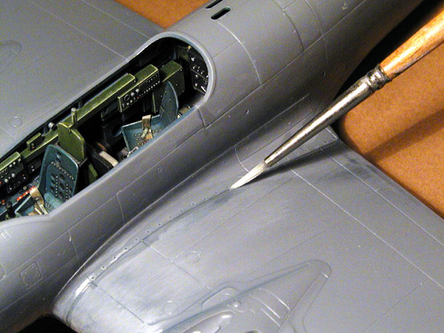
Now here is where things get weird, because the
next step is to make sure that there is a gap between the parts
because the panel line needs to prevail. I do this by slightly
beveling or rounding the edges of each mating surface. I use a sharp
hobby blade, and lightly scrape the part along the mating surface,
which will become a panel line. Take care to match the fidelity of
the original lines scribed on the rest of the model.
By beveling both sides of the intended panel
line, a nice even line will result when liquid cement is applied along
the seam. Be careful with the adhesive and the parts. DO NOT apply
any pressure AFTER the adhesive is applied because melted plastic will
pop up and fill the panel line. Any clamping or taping in place
should be done before any adhesive is applied. After the adhesive has
evaporated and the parts are solid again, go over the panel lines with
some 0000 steel wool, or fine Scotch Brite pads to smooth
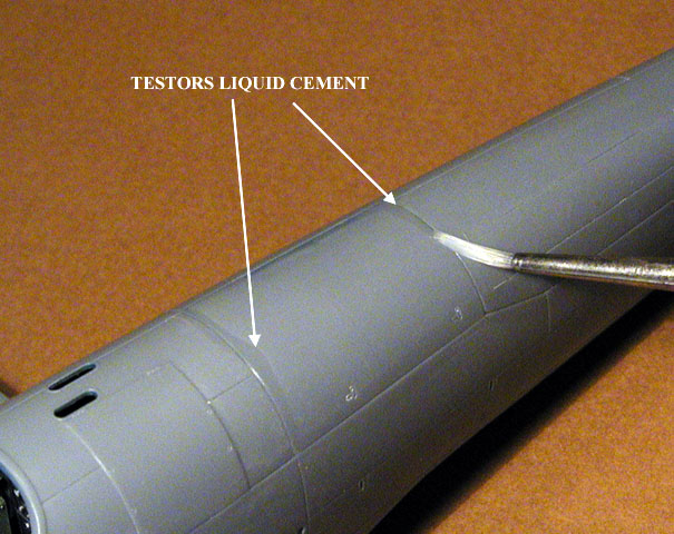
things over. As a final touch, I use Testors liquid cement
brushed on the panel line to gradually melt and smooth the line over.
Testors liquid cement takes a very long time to evaporate, but
I also very gentle to the plastic. Because of these properties it is
not a good choice on major bonds, but is a good choice for blending
and smoothing things over. I believe that Gunze also makes a
slow adhesive but I have not tried it.
If there are any gaps, Mr. Surfacer 500
brushed into the gap will fill it. Smooth over the Mr. Surfacer
with cotton swab dipped in Mr. Color Thinner or some 91%
isopropyl alcohol. When done properly, the insert should look like
any other scribing on the model.
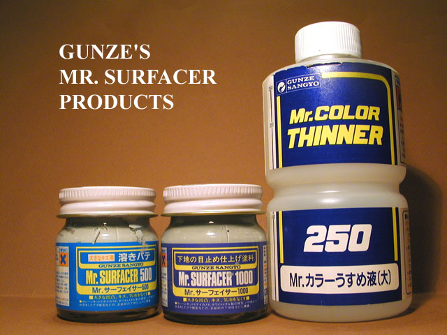
Speaking of Mr. Surfacer, I have found
that this primer/filler is an indispensable part of my toolbox. I
recommend that you investigate this product for yourself. Mr.
Surfacer 500 is a heavy bodied filler intended for brush
application to fill slight imperfections such as a little gap, ding,
slip of the scribing tool, or a good sized scratch. Mr. Surfacer
1000 is a fine-bodied primer that can be used with a brush or
sprayed through an airbrush. Mr. Surfacer 1000 is used to fill
small imperfections and slight scratches, and when used with an
airbrush it is a base coat for paint. Thinned 50% with lacquer
thinner when sprayed, an eggshell finish is achieved that dries in
about 10 minutes. You will have a hard time finding a better surface
for painting. Thin it with Mr. Color Thinner, and the sheen is
greater (semi-gloss) and the drying time increases to about 20
minutes. I love this stuff!
Wings
Tamiya’s Gekko has been reviewed in
several magazines, including Tamiya’s own model magazine. I
have seen it written more than once that the engine nacelles,
assembled separately, are attached to the wings along natural panel
lines, and can be attached to the model after all painting is done.
Well, folks, this just isn’t true. And to be frank, attaching major
structural things after painting is not an approach that I like to
take. The final quality of the model is too important to take for
granted.
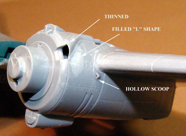
In truth, Tamiya has molded the engine nacelles
so that they are as “generic” as possible, and able to accept new
nacelles with further releases of the kit. The late versions of this
aircraft feature individual ejector style exhausts, and some revised
panel lines. The break actually falls halfway on a natural panel
line, and then takes an “L” shape inside a square panel. The “L”
shape must be filled in. The tricky part here is not destroying the
little scoops and filler hatches molded into this area.
I used Pro Weld on the joints, but did not
squeeze the joint, because it falls halfway on a natural panel line.
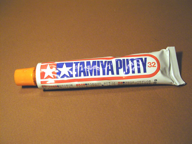
To fill the “L” shaped joint, I resorted to good
old-fashioned putty (sort of). Actually, I used Tamiya’s
putty, which is a fantastic product. Tamiya’s putty dries VERY
quickly, ready to sand in 15 minutes with thin applications.
Tamiya’s putty also features metallic particles, aluminum possibly
that give it both strength and shrink resistance. CA could have been
used here as well, but the Tamiya putty sands easier, an
important consideration around the small details in this area.
I covered all of the details with tape before
sanding the putty with wet 600 grit paper. A dab of
Mr. Surfacer 500 over the sanded area will
insure that no tiny imperfections remain. One more wet sanding, and
the operation is complete.
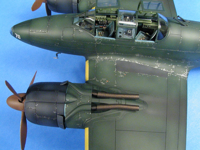
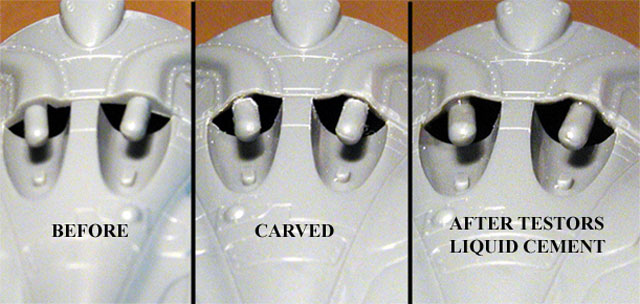
The nacelles can use some added attention to some
details as well. There are two small scoops located on each nacelle
that should be opened up. I use a sharp needle to probe the face of
the scoop, and make the beginnings of an opening. Push the needle in,
and wiggle it from side to side. Then use a sharp hobby blade to
carve the little scoop out. To smooth things over, use a little dab
of Testors liquid cement inside each scoop. On the top of the
nacelles are the stubs where the exhaust pipes attach. The area
around the stubs needs to be thinned to represent sheet metal and not
molded plastic. I used a hobby blade to carve the openings to a more
appropriate appearance. The tunnels covering the exhaust manifolds on
the front of the nacelles needs attention as well.
The cowl flaps should be thinned out for a more
scale appearance. I chose the opened flaps, but either should be
thinned. I use two methods for this. If the job is a big one, I will
use a motor-tool and sanding drum to get things down to size. But
usually, like here, I have used a curved blade, #10 in Exacto’s
line, to scrape the cowl flaps into size. Then finish with fine
sandpaper.
Underneath, things get ugly. There is a seam
that runs completely through and inside the exit portion of the oil
coolers. No way was I going to spend the time sanding this out, way
up inside a tubular structure, but it needed attention nonetheless. I
decided to use a “home brew” liquefied putty flowed in with a brush.
Mr. Surfacer 500 was not thick enough for this job! My brew consists
of an old used bottle of Testors liquid cement, about half
full, to which I have added a great-big dollop of Tamiya
putty. Mixed up, and apply with an old paintbrush. I just put a good
brush full right into the oil cooler exit hole, smoothed it around
some, and let it dry. The liquid putty filled in the seams all around
the inside of the orifice. Unfortunately, it also will fill in the
horizontally etched oil cooler detail. This area is so hard to see on
the finished model, I opted for getting the seams out over the little
bit of detail. If this weren’t an OOB model, a nice piece of
photo-etched grille would look nice in there…In the end, I painted the
whole thing black inside, and I am OK with it.
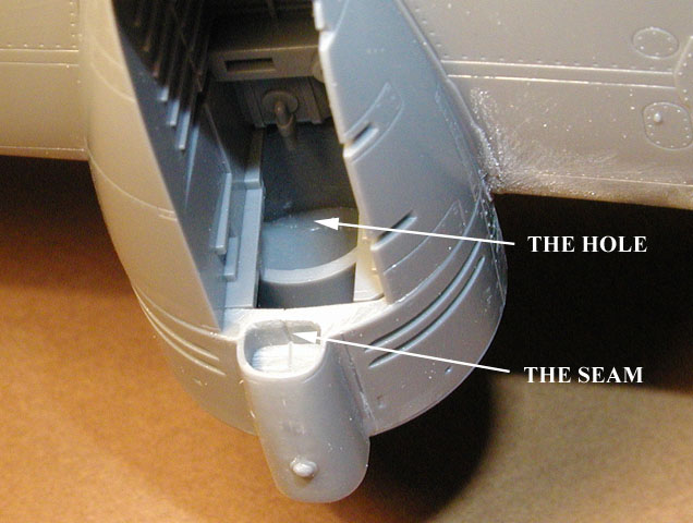
Another nasty surprise awaited me in the wheel
wells. My friend Stan Spooner has built the Gekko for
Tamiya America’s website:
http://www.tamiyausa.com/product/plastic/tips/beafraid.html
and pointed out a very interesting problem that I
had not caught yet. The front of the wheel well is completely open,
and exposes the insides of the nacelles. It is literally a great-big
hole. The gear legs hide much of this hole but anyone having a good
look will notice it. Two options for an OOB model: Live with it, or
fill the hole with an appropriate filler and sculpt/shape it to look
like the forward gear well it its supposed to be. If I had noticed
this before the nacelles were in place, it may have been possible to
fix it with epoxy putty and some formers to retain the putty’s shape
while curing. I did not wish to attempt this with the nacelles in
place because access is too limited. So, I left it. But it bugs me.
If you are not building this one OOB, you could simply use plastic
card to manufacture a bulkhead.
The wings feature separate wingtips that attach
into slots like the Mosquito kit. One article I read stated that
these tips were a problem, and tended to point upwards when attached.
I flat-filed the joints flush using the pencil method, beveled the
join line because it is on a natural panel line, and attached them in
a perfectly normal attitude with no problem, and no fit problem. The
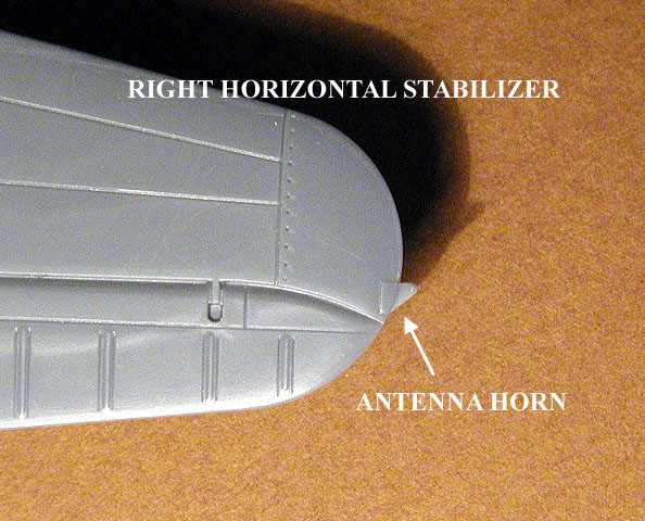
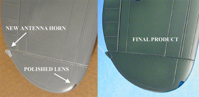
Gekko has an antenna wire that stretches from the tip of the right
horizontal stabilizer out to the tip of the right wing. There is a
“horn” for the antenna molded onto the stabilizer tip, but curiously
Tamiya has forgotten to include it on the wing tip.
I decided to shape a blob of CA adhesive on the
wingtip into the appropriate shape. A piece of tape backing up the
wet adhesive holds it there while accelerator is applied.
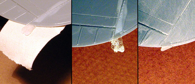
Then simply remove the tape and file or sand to
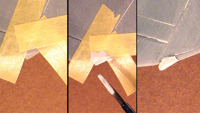
shape. Masking the appropriate area and applying a heavy coat of
Mr. Surfacer 500 simulated a fillet for the horn-attachment point
to the wing. When dry, the mask is removed, and a raised fillet is
formed.
There is a clear part provided for the navigation
light on each wingtip. I glued this in place with CA and then sanded
and polished the parts for a perfectly blended fit. Just before the
final primer coat, I masked these lights off with a liquid masking
agent to protect the finish. One of the final touches to the finished
model was painting these lights with Tamiya clear colors.
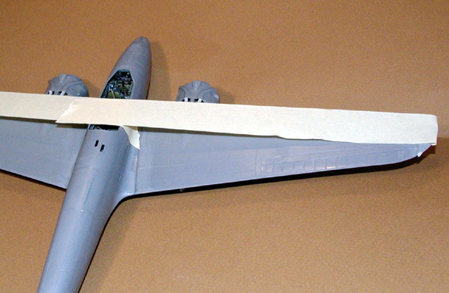
The wing join lines are molded along panel lines,
including the underside and the wing roots, so all of the necessary
steps mentioned earlier for that kind of join were carried out. Tape
stretched out to the tips was used to pull the wing root in tight
against the fuselage
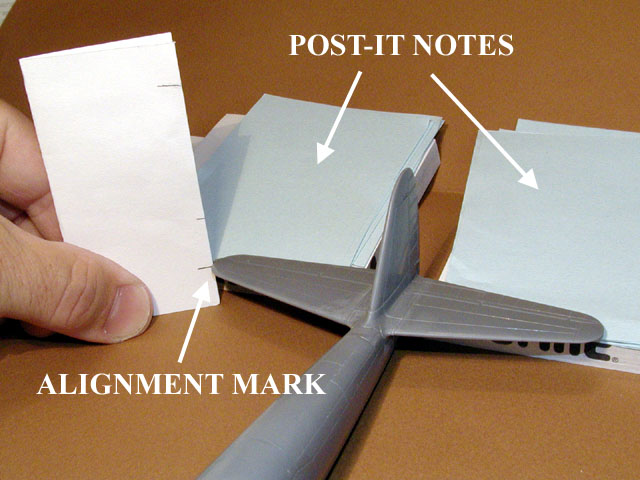
Pro Weld was used along all the joints
followed by steel wool and then Testors liquid cement in the proper
intervals. While the wing dried, it was propped level and the tips
were set on identical stacks of Post-It notes to insure that they
measured the same during final assembly. This single step is perhaps
the most important when it comes to preparing a model for a contest.
The VERY FIRST thing a judge will do, is look at the model from
the front and see if it all lines up perpendicular, parallel,
vertical, horizontal, diagonal and symmetrical to his Mk. I Eyeball.
I use a scale or a marked business card to make sure that all of the
measurements are the same.
(In Part 3, I have a story to tell about how this
particular step came back to haunt me with this model)
The horizontal stabs are molded on natural panel
lines as well, and were attached using the same method as the wings.
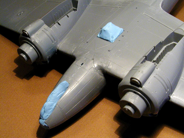
The model is now ready for primer, but the
openings in the fuselage must be sealed first. I used a blob of
poster mounting clay, sometimes known as Blu-Tac to seal the nose
glass and belly glass areas.
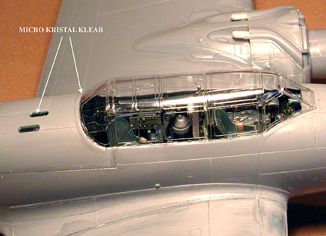
Tamiya provides a closed canopy that would
be extra on my model, so I used it to mask the cockpit area.
Microscale’s Kristal Klear was used on the edges of the canopy to
seal it temporarily. Sometimes I will install the canopy completely
before painting a model, and other times, such as here, the fit is so
good, that the canopies can be installed perfectly after painting. I
also used Kristal Klear to seal the cannon ports.
Like I mentioned earlier, I use Mr. Surfacer
1000 thinned with 50% lacquer thinner for a primer coat. I always
begin spraying at wing roots or any angle that is near 90 degrees. I
will usually spray this area with a good “wet” coat first so that any
over spray will not collect in the vortex formed by the shape and the
airflow over that area. If I did not do this, the area could end up
looking “powdery” and rough. After that, Mr. Surfacer goes on
the entire model with a moderately wet application. It is dry to
handle in about thirty minutes, and workable after an hour. Some
Mr. Surfacer 500 was used to fill some small imperfections, and
after a final check, Gekko is ready for color.
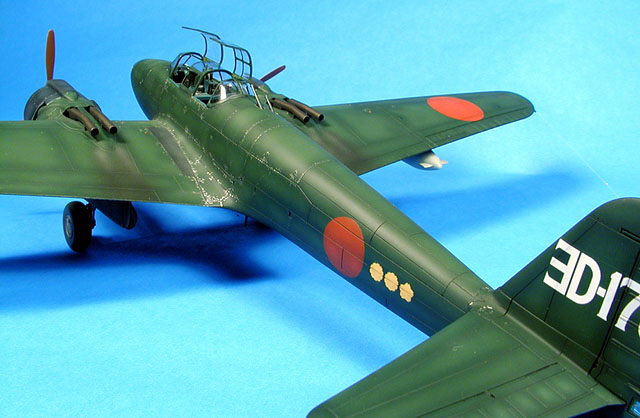
In Part 3, I will describe some painting
techniques, some weathering techniques and present the finished
model. Here is a preview…
Click
the thumbnails below to view larger images:
Happy Modeling!
Model, Images and Text Copyright © 2001 by
Gregg Cooper
Page Created 05 October, 2001
Last Updated
04 June, 2007
Back to HyperScale Main
Page
Back to Features
Index
|
 Home
| What's New |
Features |
Gallery |
Reviews |
Reference |
Forum |
Search
Home
| What's New |
Features |
Gallery |
Reviews |
Reference |
Forum |
Search