Kitty Hawk's 1/35 scale
AH-6J and MH-6J
Step-by-Step
by Floyd S. Werner Jr.
|
AH-6J and MH-6J Step-by-Step
|

Hobby Boss's 1/48 F4U-7 Corsair is available online from Squadron.com
Disclaimer: I helped develop this model. I am an unpaid consultant to Kitty Hawk. I provide them with drawings, photos, proof the CAD, and provide marking options. I like to get that out there so there is no hint of collusion. Those that know me know I’m honest so what you get here is an unbiased review. Some may not agree with that but you’ve been warned. I also take full responsibility for any errors.
The Little Birds of Task Force 160 (SOAR) are the unsung heroes of the regiment. There were two types of Little Birds, the AH-6J is the armed variant and the MH-6J is the operator hauler. The Kitty Hawk kit allows you to build either variant, but you must choose which one.
The model comes in a very sturdy cardboard box with some fantastic artwork on the top. One thing that is missing on the box top is the Werner’s Wings logo. It was just an oversight. I was heavily involved with this kit. That is Kitty Hawk’s way of saying thanks by including my logo. We just missed it prior to printing. No harm, no foul.
The kit includes three sprues. The plastic is light grey with very little flash. The detail is refined and beautifully rendered. There are some really small parts. I did find a few parts that were short shot. Contacting Kitty Hawk’s Sophia Lymn at Sophialynm@gmail.com for the replacement parts had them on the way. The rivets are recessed which some will not like, but it looks good. The parts allow you to build either version Little Bird.
The clear parts are packaged separately wrapped in a clear wrapper inside a small cardboard box. This ensures that the parts are not cracked or scratched.
Two frets of photo etch are included. One includes the ammo chutes that are required for the two guns.
The instructions look easy enough to follow and is set up in the usual Kitty Hawk manner with the color profiles in the center on fold out pages. The one thing about the instructions is that they aren’t too clear as to which parts go to which version. Careful studying is required before cutting parts. The first profile is an AH-6M which is not in this kit. Maybe at a later date.
The decals are a bit of a disappointment. They are printed in a light grey as opposed to the olive drab or black color.
Well it looks good in the box, let’s see what it builds up like. I’ll do this step by step.
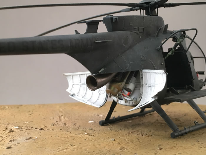
Step 1 starts in the engine compartment. The Allison C-250 is the best rendition of this little engine that I’ve seen. Where the exhaust comes out should be rectangular but when mounted you can’t notice the difference. The fit of the parts is very good. I did need a touch of filler on the exhaust stacks to make them smooth but everything looks great and just needs some painting. Various shades of burnt metal are used. The engine assembly was painted with a mmixture of Alclad, AK Metallic and Model Master which provided color variation. If you are going to display your model closed up you only need to paint the exhaust itself, Part B63. One thing to note in this step is that you may have to drill some small holes in part B1 to fit the ignitor leads.
Step 2- The engine compartment is a thing of beauty. The level of detail here rivals some of the best resin sets. Everything fits as advertised but there is one problem in the instructions. Parts B70 and B71 are mislabeled on the instructions. Just switch them around. If you look at the photos it is easy to understand what is being called out.
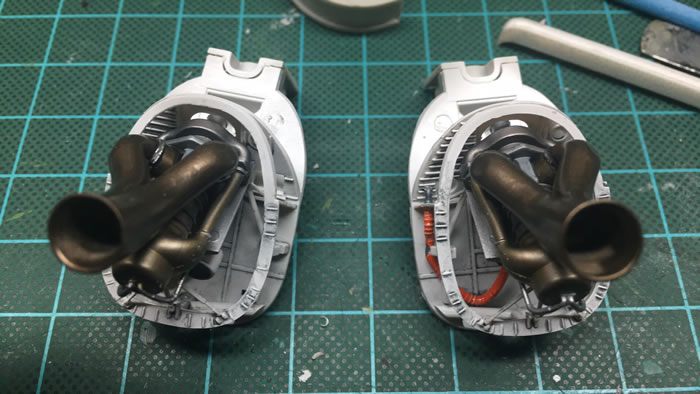
Once you understand that everything fits perfectly. The engine compartment is flat white. Pretty plain but simple to paint. If you are going to close up the model, then you don’t even need to do that.
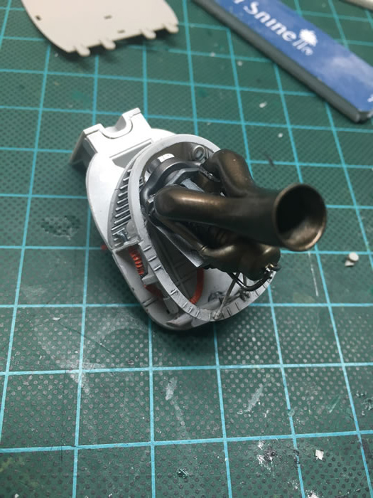
My engine compartment is painted with Alclad White Primer and weathered with Mig Cold Grey Wash.
Step 3 is the beginning of the cockpit. It is also contains the first short shot part. Part C54 is missing the very bottom of the stick. It is barely noticeable but shouldn’t have happened. Another thing that I noticed which was annoying is that part C57 is a mirror or part B58. It should be exactly the same. I had two kits so I used one from another box. The other kit has the wrong parts but at least they are the same shape. One error in the instruction is that C57 should actually be B57. C21 and C20 are the side mounted screens on the side of the instrument panel and are only installed when the FLIR is installed. The kit doesn’t include the FLIR or mount. One side of the instrument panel is lacking a hole. It is easy enough to add with a drill bit if you want to add the detail or filled if you don’t but shouldn’t have happened. Since my MH didn’t have the FLIR installed I filled the holes. The rest of the step is nicely detailed.
I recommend that you paint the entire cockpit assembly Tamiya NATO Flat Black. The instrument panel and center console are provided as decals. I thought I’d check out how they worked. After carefully cutting away the decal clear film I could then use the decals normally by adding the decals to the instrument panel right over the kit detail. My technique is to slide the decal off the backing paper and through a puddle of Future. The carefully apply it to the model. I let it set up for about an hour. Then apply a coat of Solvaset and let it dry thoroughly. After it dried, I used a brand new #11 Xacto blade and pierced any bubbles and reapplied Solvaset until the decal had set down completely. It is amazing that the detail matched up perfectly. This is not the first time that Kitty Hawk has done this with the same amazing results. The entire assembly is sprayed Alclad Flat, then the gauges were highlighted with drops of Micro Krystal Kleer.

Step 4 continues with the cockpit bulkhead. I made a mistake and missed the avionics above the pilot’s seats and behind them while proofing them. I’m sorry. I’m working on it. DO NOT REMOVE THE LITTLE TABS on the side of A50. These are mounts for the fuselage halves later and easy enough to remove if you aren’t careful. Assembly is easy enough. Part B32 which is the cockpit light does require you to drill a hole because it isn’t on the kit. Assembly of the seats is pretty impressive, but you must follow the assembly sequence. Add A-18/19 to the floor but DON’T REMOVE the support rods from these parts. They are needed to support the seat. Then add the seat backing, A63 and A64, before you add the seat bottom A27/A28. I left the backs and bottoms off until I put some paint under and behind them. The seats can be either flat black, faded olive green or a combination of the two. The seatbelts can be green, black to a faded deck tan.
Step 5 is the rudder pedals and again we are presented with a short shot part. One of my part B49 is missing the actual pedal. I made my own with some brass tubing that was sanded down to shape and cut to shape. I was pretty impressed with my scratch building but what bothered me is why I should have to do it on a brand-new kit. The other issue with this assembly is that rudder pedals don’t have holes drilled in them to fit part B41. You can handle it a number of ways, I drilled holes that addressed what should have been there. Another option is to cut of the tabs off of B41 and flush mount them. Either way works. The parts are really small and a pain to clean up but take your time and you are rewarded with a beautiful assembly.
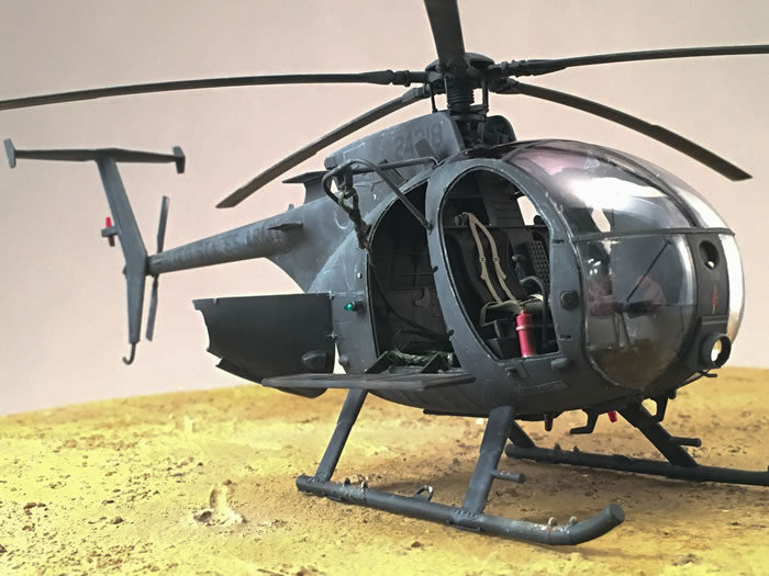
Step 6 is only required if you are building the AH-6J. I am doing one of them as well, so I cleaned up the platform. The placement of B12 and B11 are a little vague but if you look at the instructions it is pretty clear. One thing that is not quite correct is that the end armament platforms, C22 and C23, should be solid and not cut out. The cutout is on the short version of the platform. It is easy to modify if you want the short version just sand off some of the attachment arms. The ones in Somalia are the longer type so I added some .040 plastic to fill the hole. Everything fit perfectly.
Step 7 is for the MH-6J version. If you follow the instructions, they would have you add the benches in this step. DON’T! DO NOT add the benches at this time. There is no way to put them through the doors once mounted and you’ll just have to break them off. One note about this step is that A20 and A21 are mis-marked on the instructions, as are A5 and A6. A20 and A21 will only fit one way so no real issue. The key with A5 and A6 is there is a small cutout on them. It should be facing aft to fit properly. I recommend that you add A20 and A21 to the floor now and build up the benches and their supports at this time then set them aside. If you are going to add the fuel tank, then make sure you open the holes in the floor.
I took the time to paint the interior, including the fuselage halves and doorways, now BEFORE I added the canopy. Tamiya NATO Black was painted overall. Then a panel line wash from AK Interactive for Black Camouflage was added to the panel lines. Allowed to dry slightly and then a slightly damp flat brush was used to blend the excess around the interior. This gives a nice used look. Some sponge weathering was used with Model Master Magnesium and some silver pencils. Some Mig Pigments for North Africa was used to add some dirt to the floor.
Step 8- Add the fuel tank if you are going to. I didn’t need to add it to my MH as it appears that the MHs in Somalia didn’t have them. Assembling the cockpit and the rear bulkhead is a very sturdy assembly. If you are doing the AH version, it is a good time to add the armament bench. Don’t forget to open the hole for the fire extinguisher regardless of version.
Step 9 will require you to open some holes on both fuselage halves prior to assembly. Make sure you open up the correct holes. Parts A4 and A2 are for the MH FRIES mounts but are on all versions of the J model Little Bird. I deviated from the instructions here. I added my tailboom halves to the corresponding fuselage halve. This proved to be an easy way to ensure alignment at this time. PE8 barely fits the hole so be sure to add it before you close up the fuselage. Another thing that I recommend IF you are going to have the engine cowlings closed is to add the engine compartment access doors to the fuselage halves at this time. Do it now while you have the ability to align everything. When you bring everything together the fit is remarkable. There are tabs on the bottom of the fuselage halves that aid in the process. Another recommendation is to decide which type of intake is going to go on the left side and install that part now and not at Step 15. This allows you to work it should you need to. Also, it allows you to add a small backing plate for PE-9 as the fit is very loose.
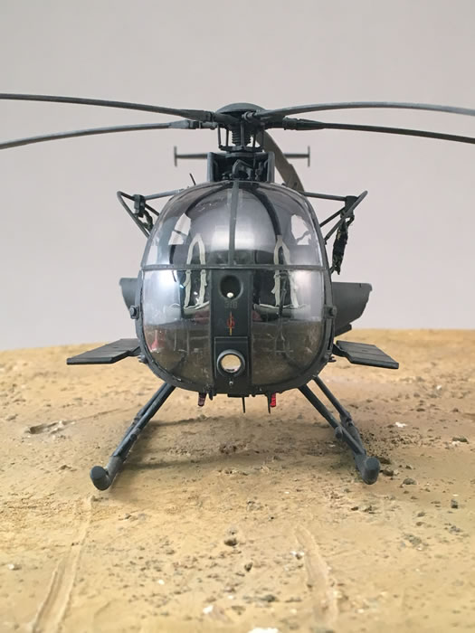
Step 10 has you adding the windscreen. I masked off the rear portion of the canopy and sprayed AK Smoke on the inside. BEFORE you add the canopy don’t forget that you have to add the magnetic compass to the clear canopy. The instructions are vague at best where to add the compass and has no mounting point. I painted the compass then used Tamiya cement, not the extra thin type, and very carefully added a stripe of it to the compass and added it to the canopy. It worked perfectly, however, I think I have my compasses a little bit too high. It should mount just above the instrument panel. I did have to sand the front of my instrument panel while test fitting the canopy, but it is no big deal and hidden once the canopy is added. I also sanded the back of the light housing which is on the clear part. Once all that was done the canopy fit really well. I used some Tamiya cement to hold things in place then used Tamiya tape to hold it all together while I added some Elmer’s White Glue to the entire circumference of the window. Once everything dried I used a cotton swab and blended and removed the white glue from the window.
Step 11 is building up the M-134 guns. This is a pain in the butt. I decided to build mine up from tubing instead of the plastic parts. That meant that I didn’t have to clean up the mold lines. Using the kit parts as patterns I used Albion Alloy telescopic tubing cut to length. The photo etch flash suppressor, PE6, requires you to bend it. Here is how I did mine. I first cut off the round end caps. First off you only need one end cap. I set them aside and used my Small Tools SMS006 Photo Etch Bending & Rolling Deluxe Brass Assist. It is expensive but so worth the money, especially on a project like this. I finished rolling this so that it was circular and held in place with some superglue. Then I was just a matter of adding one of the end caps and attaching it to the tubing. I think the next time I do it I’ll use Live Resin M-134 minigun barrels. So much simpler. The guns themselves go together remarkably well as long as you take your time.
Step 12 is the GAU-19. I did not build up the
GAU-19 as my AH-6J didn’t need it.
Step 13 has you add the guns. Don’t do it at this time. It also has you build up the landing gear. Some have complained about the landing gear being multiple parts. I like the ability to add either type of skid. Some have questioned whether of the skids are the thicker type used on the A/MH-6M, if they are then it isn’t obvious to me. I know I provided the measurements from an actual aircraft. The fit of the landing gear tips was good. Adding the skids to the model was pretty easy. The mounting areas are a little small but attached well enough with Tamiya cement. I used tape to hold the gear down and then used a sanding stick on top of the housing to make sure the top of the model was parallel.
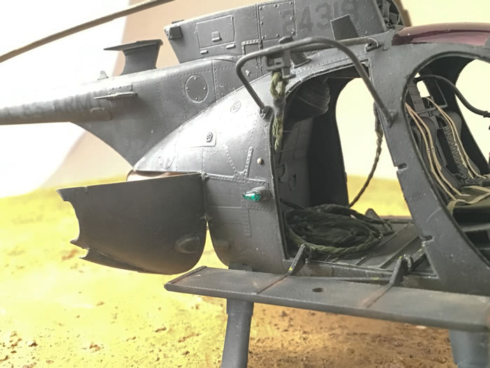
Step 14 concentrates on antennas and ammo chutes. Since this was an MH-6 I didn’t need the ammo chutes. You have to look at your subject to figure out which antennas to use. I left the doors off as they are not installed on operations. There were no issues. Antenna, A33, seems a little large. I used a Werner’s Wings APR-39 blade antenna where A33 goes.
Step 15 adds the other side of antennas. One thing that was left out for some reason was the sail type antenna. I raided the Dragon/DML kit for this antenna. We proofed it but for some reason it didn’t make the kit. Werner’s Wings is working on that as well. The upper portion of the doghouse gives you two options. My option was the plain type but the square antenna on it that is shown on the instructions is not included. I added one made from styrene. In case you didn’t add this back at Step 9. There are two types of plugs for the left side depending on your subject. My MH didn’t have the inlet scoop, so the flush mount was used. Before you put A54 on I recommend that you add a backing plate for the PE part, PE9. The fit is really loose. The mounts for the FRIES are added at this time. Pay attention to the drawings to see how they go. I have mine slightly off but decided to live with it. The landing light is installed. There is a hole for the FLIR mount but since no FLIR is included I had to fill the hole with Apoxy Sculpt. While that was drying I added a pitot tube from Albion Ally tubing, which for some reason is not included in the kit even though it was on the CAD. Another thing missing is the IR formation light inside the vent on the inlet on the nose. Luckily, I had some from Werner’s Wings that I added. You could always do the same thing with a little bit of Elmer’s Glue and toothpick.
Step 16 is the tailboom portion. I added mine earlier in the build as part of the fuselage halves. This made life easier for me. The vertical tail was built up by adding the end caps first which is just a butt join. After drying the vertical part of the tail was added to the horizontal. You have to decide which lighting assembly to use as there are two different types. One of the things that is ‘interesting’ is that the rear mounting lugs are not included in the kit, but they are shown on the instructions. I used some .30 tubing to add them, but you shouldn’t have to do that.
Assembling the tail rotor gearbox is easy if you take your time. The key is to line up the mounting points. The tail rotor assembly was a pain to put together. The first thing to do is to be careful when removing A32, the tail rotor crosshead, if you cut off the mounting point inadvertently all is not lost. Leave a little bit of a tab to mount in the hole. Then there is the clean up of the pitch change rods and the corresponding tabs on the blade assembly. If you clean them up they will slide together perfectly. It took some time but was doable easily. I set my tail rotor aside to paint separately.
Step 17 is the main rotor controls and swashplate assembly. The very first thing to do is to drill the holes in part B78 to mount things to. Mine had one hole in the part but not in the other three holes. Once you do that the build up of the swashplate is easy. I recommend that you DON’T add C56 and A47. These will be added in the next step with the blades and make it easier to have them removable. When built up the swashplate assembly is perfect.
Step 18 is the rotor assembly. I cleaned up the hub, A46 to make sure everything sets solid. The blades are very secure when adding them to the hub assembly. Since I didn’t add C56 and A47 now was the time to bring them together with the hub. Here is how I did it. Using A47 to align things up. Add C56 to the hub, A46, and allow to dry completely. Once dry add, B40, the pitch change links. They will allow you to mount the swashplate to the bottom of the PC links and end of the swashplate. The PC links fit into the end of the swashplate. If done properly they will line up perfectly. Now you can remove the blade assembly.
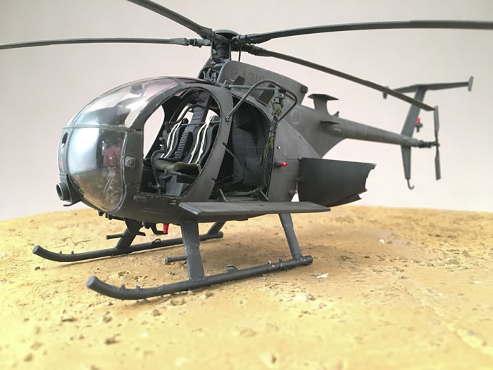
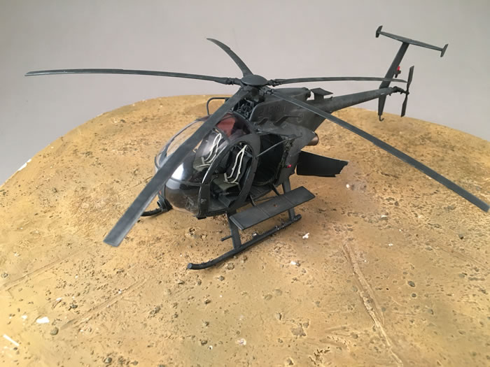
Painting is where things start to look great. I painted things as I went along because there are some areas that need to be black underneath or behind. Tamiya NATO Black is my go to black color. It isn’t too dark. I used plenty of shades of black and dark grey throughout the build. I used Tamiya tape to mask off the cockpit. The huge doorways were masked off with the clear doors, which were attached with white glue to tack them in place. Then the canopy area was sprayed with Tamiya NATO Black. The whole model then got a coat of Alclad Grey Primer. The model didn’t need anything else. Other than a little bit of white glue around the canopy I can’t remember using any filler on this model. Which to me is amazing. So, without anything to clean up I painted the entire model with the Tamiya NATO Black. The upper surfaces and some panels were highlighted with Tamiya German Grey. This put some variation in the paint.
A coat of Tamiya Clear was added over the model to prepare it for decals. I had a picture of an aircraft that I wanted to do. Little did I know that the picture was taken during the filming of the movie, “Blackhawk Down” instead of at the actual mission. I didn’t find this out until later. Actually, as I was building this model a wave of new information was coming out on GOTHIC SERPENT, especially the Little Birds. Most of the tail numbers have been identified but what really came to light was that the markings were black and not olive drab as previously thought. I ended up using decals from the AOA Decal sheet Loach in Vietnam. This provided all the markings I needed with the exception of the olive drab number on the nose and the Six Gun markings which came from a Werner’s Wings sheet. I’m debating on releasing a GOTHIC SERPENT specific sheet since we have most of the information now. Anyhow the decals are printed by Cartograf so they worked perfectly.
I wanted something different for my MH. I thought about adding the FRIES ropes as they were installed on the subject aircraft. I was going to use some 110-parachute chord, but it was a little too big. What to do? I racked my head then realized that the inside of the chord there was another chord. I pulled it out and was really pleasantly surprised to discover a great looking rope replica, but it was white. I used a lighter to ‘melt’ the end of the rope so it wouldn’t unravel. I threaded the ‘rope’ through the FRIES mount and then bent it over on itself and used super glue to attach the rope to itself then some Tamiya tape to replicate that feature. The rope was painted with Gunze Marine Corps Field Green and the tape was painted Lifecolor Satin Black.
I sprayed Alclad Flat over the entire model.
Now that I had a black helicopter it was time to add some life to it. Using the AK Panel Line Wash for Black Camouflage I painted it in the panel lines. Then I removed the excess with a flat brush slightly damp with turpenoid. I swirl it around to get it mixed up and then I drag it down vertically to simulate rain streaking. Once it was dry, I used Titanium Buff and Titanium White artist oils as a dot filter. This fades and imparts rain marks as well. I did some chipping with Model Master Magnesium with a sponge and then a #2 and silver pencil. Some Mig Pigments were added here and there to ‘attach’ it to the ground. Some Tamiya weathering pastels were used to weather the top of the model.
Rotor blades weathered with silver underneath, Tamiya NATO black on top of that. Then using Model Casters sanding sticks I wore out the leading edge. This was touched up with Model Master Magnesium dry brush. Then some Tamiya modeling pigments.
Then another light coat of Alclad Flat was sprayed over everything to seal it and to unify things.
The masks were removed and the canopy polished inside and out. The clear parts were added. Clear red, green and smoke were added to the appropriate parts. The final thing was to add the benches and the engine access doors. Tamiya cement plus some tape held them in place while they dried.
Overall this is a very nice kit that builds up beautifully, but it does require some modeling skills. Basic skills but still skills. It is not a shake and bake Tamiya kit. There are things that Kitty Hawk did or didn’t do that made me scratch my head. Some things are my fault and for that I’m sorry. The kit is not for a beginner but even a moderate modeler can make this into a winning kit. Kitty Hawk continues to improve with each kit, especially their helicopter kits, but there is still some room for improvement. I can’t wait to see what they do next.
Take this review and make notes in your instructions and you shouldn’t have any problems. I’ve got the AH in construction. Werner’s Wings is coming out with the downward exhausts and some other upgrades for the kit. The kit decals are disappointing. I hope that I will be able to fix that too.
Bottom line, I had a great time building this kit and really enjoy what the end product looks like. I can’t wait to finish up the AH-6J. I’ve really enjoyed building Kitty Hawk’s kits.
One last disclaimer, I helped Kitty Hawk design this kit. I had more than a little bit to do with it. With that said, I think you can see from this review I don’t pull any punches with Kitty Hawk or myself. You get an honest and upfront review. Use it to make your build easier. I don’t claim it to be a perfect kit but it one of the best fitting kits I’ve built.
Thanks to Kitty Hawk for the review copy. Check your local hobby shop or online retailer to obtain your copy
Suggestions for Improvement
Here is my list that I provided to Kitty Hawk to improve:
-
Missing the Avionics behind seats
-
Missing Avionics shelf above the seats
-
Sail antenna on the tailboom not included
-
IR light inside the nose opening is missing
-
APR-39 antenna on the belly is missing
-
Square antenna on the doghouse missing.
-
No FLIR or mount
Text and Images Copyright ©
2018 by Floyd S. Werner Jr.
Page Created 9 May, 2018
Last Updated
11 May, 2018
Back to
HyperScale Main Page

|
Home
| What's New |
Features |
Gallery |
Reviews |
Reference |
Forum |
Search