Classic Airframes' 1/48 scale
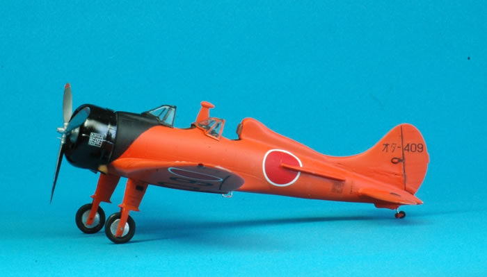
A5M4-K Claude Trainer
by Andrew Garcia
|
A5M4-K Claude Trainer
|

Hobby Boss's 1/48 F4U-7 Corsair is available online from Squadron.com
Summary
Kit: Classic Airframes A5M4-K Trainer
Kit # 438
Price: $29.95
Decals: Two Aircraft Versions – Microscale printed
Reviewer: Andrew Garcia
Notes: Challenging build but a unique variant will be your reward
History:
The Mitsubishi A5M also known as the Mitsubishi Navy Type 96 Carrier-based Fighter was a Japanese carrier-based fighter aircraft. It was the world's first monoplane shipboard fighter to enter service and the direct predecessor of the famous Mitsubishi A6M "Zero". It was manufactured by Mitsubishi Heavy Industries, Ltd and designed by Jiro Horikoshi. The first flight of the A5M was on February 4, 1935 and it started or was introduced to service in 1936. Although it served until the end of WWII in 1945 with the Imperial Japanese Navy Air Service it was no longer an effective airplane. Although the total number of A5M Claude’s built was 1,094, no versions have survived save for a few found underwater in a Pacific lagoon on the freighter they were stored in while being transported to their final destination.
The version modeled is the two-seat trainer version of the A5M4 model known as the A5M4K or A5M4-K. The A5M4-K Two-seat Trainer was first produced by Watanabe Iron Works in May 1942 and 103 were constructed by the Naval Ohmura Arsenal.
The Kit
Classic Airframes kits are limited run injection plastic kits with vac-formed canopies and resin detail parts. Decals are printed by Microscale and were in perfect register and worked well. Due to their age I used Microscale Liquid Decal Film to clear coat them before use to prevent shattering. I am a big fan of Microscale printed decals since they are thin but not too thin. The kit plastic parts required clean-up and a great deal of test fitting during assembly. Cockpit resin parts were reasonably detailed but did not fit well and required rework.
Recently, builds of the new Wingsy and Fine Molds A5M kits along with a release of three beautiful decal sheets from Lifelike decals prompted my taking a look at building a few A5M’s in 1/48th scale. After getting the Fine Molds and Wingsy kits, I was curious how they compared. I also wanted to have the very unusual two seat trainer version released by Classic Airframes in 2000, that I have had in the stash for over eighteen years. My secondary goal was to be able to compare the three different manufacturer’s products, that is, the Classic Airframes and newer Fine Molds and Wingsy kits. I enjoyed the project so much I also built two of my old Fine Molds A5M’s from the stash.
Only Classic Airframes has released the two-seat A5M4-K version in 1/48th scale and I doubt we will see one in injection molding from another supplier soon. It would make me very happy to see one from Wingsy or Fine Molds using their current superlative engineering and mold making. So, keep the faith but in the meantime this is your only option so go build one. They can be found at some on-line retailers and frequently on eBay as well at reasonable prices.
This is a limited run kit. Constant dry fitting, removal of material and non-gluing test assembly is required to accomplish the build. Don’t let this stop you from building this or similar kits, the end result is well worth the extra effort.
There are no locating pins or positioning tabs to help with the assembly of parts. Throughout the build I used small pins made by cutting thin but firm guitar wire to strengthen the attachment points. Some parts, used larger paper clip metal pins. Mating holes were drilled in the opposing surface faces and the pins and contact area glued with the cyanoacrylate gel. Cyanoacrylate glue was used for most of the construction. I always use this glue with metal pins when joining two surfaces subject to snapping from any torsion or material stress. Testor’s liquid glue was used for joining most of the plastic parts.
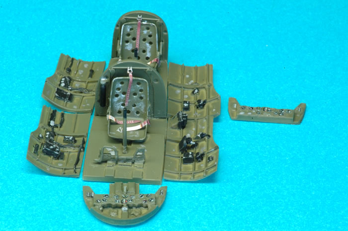
I followed the kit assembly sequence. The first step is assembly of the resin cockpit. The diagram indicates it should be assembled into a one piece unit and inserted into the fuselage half in step 2. Having built several Classic Airframes kits in the past I was aware the resin does not always fit as expected and some trimming and multiple dry-fitting is required. Thinning of the lower edge of the cockpit tub was required to allow the two fuselage halves to close. The kit instructions guide you to complete this area as a single "tub" with sidewalls attached to the floor. This is then sandwiched by the two airframe fuselage sides. After removing copious amounts of plastic from the side walls and large amounts of resin, I made the tub fit properly but lost some instrument panel details to make it all fit.
The cockpit instrument panels are nicely represented in resin. The front instrument panel is different than the rear panel. I detailed them using a combination of AirScale 1/48th Cockpit Decals AS48JPN WWII Japanese Cockpit Instrument Dials and some Mike Grant instrument decals. I looked at using the Yahu instrument panel as well. While the Yahu instrument panel is a beauty it is slightly larger than the Classic Airframes resin part. I don’t want to struggle with closing the fuselage halves and despite the Yahu part looking so good, the potential requirement for two of them for one build, and determining the Yahu could only replace the front cockpit panel and not the rear which was different, I went with the kit parts. With the added potential non-fit confirmed and fixed the kit instrument panels with decals route worked best. The cockpits are small and tight so very little is visible unless you have a small contest flashlight and make a determined effort to look inside. Despite the fit problems, it does buildup into a well detailed cockpit.
There is a nicely cast resin tail wheel. I only used one part of it – the wheel and not the leg portion. My experience with long resin pieces used to support even a small amount of weight has been poor. I replaced the tail wheel leg segment with Albion alloy tubing. This is best done before closing the fuselage halves so it can be securely fastened and adjusted.
The A5M4-K has a nicely done resin engine featuring finely cast resin cooling fins and petit overall detail. While it is a tedious assembly step requiring cleaning out every location on the crankcase where the cylinders sit due to resin leakage it did not take long to assemble the engine with gel cyanoacrylate glue. The push rods and spark plug ignition wires were added since they don’t come with the engine. Unlike some Quickboost aftermarket resin engines, where the ignition wiring harness is usually missing, the kits resin (cast by CMK) engine face includes a nice ignition harness that permit you to easily attach the spark plug ignition wires to the circular resin piece. The cylinders were painted flat black and silver dry brushing was used to highlight the cooling fin details. Significant thinning of the cowl and reduction in size of the cylinder heads are also needed to fit the assembly inside the cowl. Everything else went in fairly smoothly with more test-fitting, putty, and sanding.
While looking at some builds on the web I noticed some things that could be incorrect so I started a list of what I needed to do or avoid doing while building the A5M4-K. This usually happens because good references in English are hard to find for the A5M airframe. Most of the A5M reference texts are in Japanese. If you are not able to read Japanese your modeling accuracy could be affected. There are two superb references in English for the A5M Claude.
1) The Mushroom Models Publications #6107 A5M Claude by Tadeusz Januszewski and
2) Air Enthusiast Vol #19 pages 26 to 43.
These two references really helped my build. Another book utilized to a limited degree was the Maru Mechanic books which I used for obtaining a detailed understanding of any part of the airframe. I hope someone translates the Maru Mechanic books to English someday since they are outstanding reference and in their own class of valuable superb modeling tools.
What did I see that looked wrong on some of the CA 438 A5M4-K kit builds? Gathered from reading the kit instructions and my references some suggested things often missing from the kit builds were:
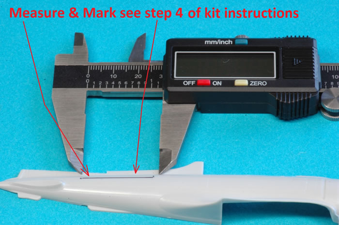
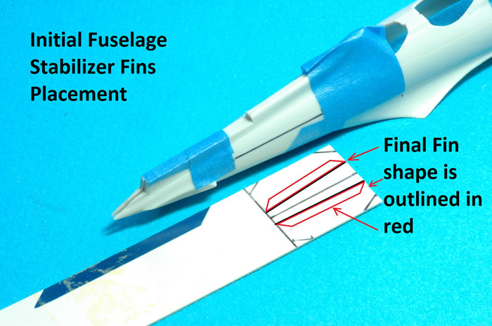
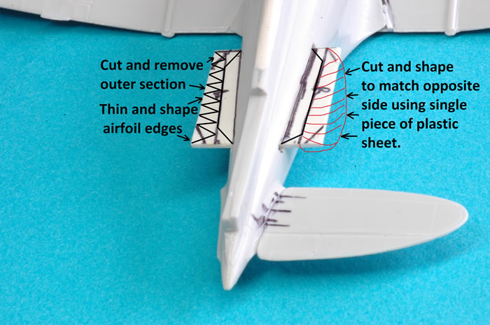
The fatal flaw – most builds (not all) on the web and the Classic Airframes kit # 438 fail to have the fuselage stabilizer fins, which were a prominent feature of the A5M4-K two seat trainer. To their credit Classic Airframes does mention this in the instructions, step # 4, but it did not help me since the drawing in step # 4 did not have this as part of the artwork. When I started the build I read this instruction note during a quick scan of the instructions and kept going on to the initial kit examination. The kit instruction is quite informative once you understand what they are describing:
“NOTE – A5M4-Ks had an airflow fence on both fuselage sides which would have been impossible to mold at scale thickness. These should be made from .010 styrene using this full size template below. See the side view drawing opposite for locating fences. Install the fences after applying the decals, using white glue. “
When I first saw the spin recovery strakes in photos I thought it was a hash mark or airframe marking because it appears as a black slash on the fuselage sides in the clearest photo of the A5M4-K used by every reference book. After more reading and photo studies I could see it in the reference photos – if you look for it. This was confirmed in the texts on page 48 of the Mushroom Models Publications #6107 A5M Claude reference and on page 43 of Air Enthusiast: "and to improve spin recovery characteristics substantial strakes were added to the sides of the rear fuselage.” This fin is missing from the kit plastic and from most of the builds I found on the web. The fin does appear in the Classic Airframes kit instructions in the four-way drawing as a line in the side view but does not appear on the top and bottom view where it would be a prominent extension from the rear sides of the airframe. The kit instructions also has a small template drawing to guide you in scratch building the strakes.
The kit instructions show the center roll-over pylon but it is too small in the drawing. You can see from actual photos it is taller and the kit plastic looks correct in size so no fix was done to this part. Don’t trim or cut the kit plastic to match the instruction drawing. Just clean up the part with a file and sanding stick.
I added a headrest or pad to the pilot’s seat back on the overturn support behind the second seat (the instructor pilot sat behind the trainee). A simple rectangular-cut piece of plastic sheet painted leather brown was attached. Why? My suggestion is based on drawings found in Japanese language references and from photo sources. It is missing from some web builds since it is not a part of the Classic Airframes kit materials.
Remove the arrestor hook and also remove the underside fairing in front of the hook. Section # 5 of the kit instructions notes this “A5M4-Ks were operated without tail hooks. Remove this fairing on the fuselage underside.”
The CA kit is the only A5M4-K in 1/48th scale I am aware of so maybe the builds I found on the web with the hook and fairing were intentional? It does look more interesting to have a hook or perhaps most of us do not read the kit assembly instructions very closely. I am often guilty of that. IN any event for accuracy delete the hook and plastic fuselage arrestor hook fairing.
If you are a perfectionist, and I am not by the way, you may want to re-scribe the kit panel lines. The CA kit panel lines did not match the drawings I used. For example, there is a small section that looks like the door used on a spitfire for pilot entry and egress. Although I do not think this feature, a door used for pilot entry and egress was on the A5M, there is a panel line in drawings representing the shape of the metal skin around the cockpit that is not on the kit plastic. It looks just like the spitfire door panel lines on accurate drawings found in the references and also in the glossy color paint diagram that comes with the kit. I enjoyed Classic Airframes inclusion of glossy paint guides matching the kit supplied markings rather than grayscale drawings usually found with other kits instructions.
Since the machine guns were removed from the front pilot station (the front trainee location) you need to fill in the shell ejector ports on the underside of the wing and remove the gun butts from the kit resin front instrument panel. Also, gun removal means you do not need to have the telescopic sights, i.e. the long tube in front of the canopy. I would think by the time this trainer was in use gun sights had evolved from telescopic sights to something like the reflector sight used in the A6M Zero, so not using outdated technology during training was a given. However, no replacement reflector gunsight was apparently used.
You may want to not add the drop tank to your model. Why? None of the photos I found in the seven references I used had any photos of an A5M 4-K Claude with drop tanks. Possibly there was no expectation they would be flying that long or that far in a training session. Also, there would be a chance of added combustible fuel to deal with in the event of a crash that happens often to trainer aircraft. I did not read from any reference that the A5M4-K version did not use or did use them so do as you please with this caveat in mind.
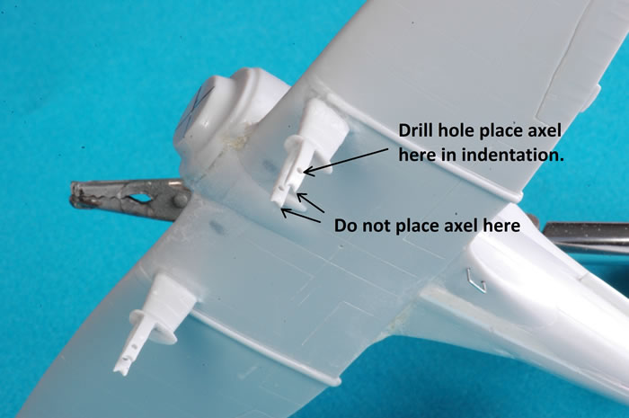
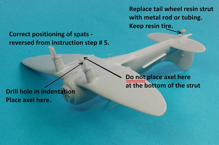
The kit landing gear legs offers two versions, one with and one without spats or the usually seen partial spats. All of the A5M4-K photos I saw only had partial spats. Photos of the spats removed show the axel is above the bottom of the landing gear spat leg and not at the very end of the landing gear spat. There is an opening at the bottom of the kit landing gear that looks like the place to put the axel of the wheel. I too thought it went there when I was looking over the kit plastic parts. It appears like that on some builds you will see – that is, the axel was placed inside the groove at the end of the landing gear plastic by some modelers. However, it is not correct and the kit plastic does have the indentation for an axel and wheel placement on the landing gear leg just above this spot.
You should drill out the hole in order to place your axel in the correct location. See Koku-Fan FAOW # 27 A5M page 41 for a close up photo of a spat-less landing gear airframe. Also, the color cover illustration on Maru Mechanic #49 11-1984 A5M shows how the axel is above the bottom of the landing gear spat. The best reference for this are the blueprints (!) of the landing gear assembly and photos on Maru Mechanic #49 11-1984 A5M on page 28. That was my source for this observation and conclusion. The landing gear leg does have an unusual extension, with a hook-like end, that is sometimes used in error as the axel location on the kit plastic for an axel. So, be mindful not to place the axel there as I saw in some builds on the web.
There appear to be many variations of the spats. The Maru Mechanic #49 1984/11 cover and cutaway drawings show the removable sections of the spats. Based on a review of the photos you do have a choice in the variety of spat sections that are removed or can be removed. Koku-Fan FAOW # 27 1991-3 has a full page photograph of the A5M4-K on page 13 that is the same as the first version of decal markings that come with the kit markings. The color kit paint diagram shows a complete or standard spat. The large reference photo in FAOW #27 shows the upper spat section missing, as well as the front tip and rear trailing cone removed. The kit no spat/exposed wheel landing gear does not represent the photo but it looks like any variation could have occurred at some time with any given airframe.
The Classic Airframes kit #438 instructions, section # 5 has the landing gear spats, parts A4/A5 & A-11/A12 facing rearward in the assembly step illustration. That would be incorrect if you follow the instructions. Just reverse them. The long portion of the landing gear leg should face the front (see photo illustration) or leading edge of the wing or nose of the airframe. Also, the instructions fail to indicate you need to provide the axel to mount the wheels. I used a section of metal paper clip for this part.
Remove the two machine gun butts from the resin front cockpit instrument panel, part R6. The kit instructions mentions this in step # 1. Fill in the two machine gun shell casing ejection chutes on the underside of the wing.
The resin tail wheel is very delicate and prone to snapping once attached. I recommend you just cut the resin rod section of the tailwheel and replace it with a metal paper clip segment or Albion alloys metal tubing.
I did not enjoy using the kit propeller. I would have preferred the entire prop was molded in plastic with just the tip or nose of the prop hub in resin. Resin does provide added or crisper details to better simulate the actual airframe prop nose. CA chose to provide three prop blades in plastic which are then attached to a complete resin prop hub in step 6. You must provide the connecting pieces to attach the final assembled prop to the kits resin engine. CA’s approach can result in incorrect prop blade angles and also an incorrect mating of the three blades to the hub resulting in a poor looking propeller assembly.
The engine cowl to engine assembly is a tight fit – too tight. You need to dry fit and remove a lot of material from the engine resin pushrod rocker tops for it to fit inside the cowl. The resin engine, as in most Classic Airframe kits is a multi-part assembly. This provides exquisite petit detail for parts such as cooling fins and detailing not present on most injection molded kit engine parts. It is a bit tedious to work with removing the individual cylinders from the pour stubs, sanding and fitting them, followed by cleaning out the crankcase depressions where the cylinders fit - before gluing (don’t wait to find out the hole has some resin overrun inside preventing the cylinder from sitting correctly while you are attaching them). I added pushrods to the resin engine cylinder heads from plastic rod and used copper wire for the spark plug wires to the resin engine.
I used many metal pins during the assembly since the kit plastic does not provide location or alignment tabs or parts. Some small parts required thin guitar wire. Larger parts I found were better connected using large diameter paper clip metal rods if they were subject to any handling or stress that CA glue was never designed to resist.
In general the kit cockpit had adequate details. When the kit was released the cockpit was impressive and considered excellent because it was far superior to most kit injected plastic instrument panels and sidewalls. Today, both resin replacements and injection plastic have come a long way and make the CA resin instrument panel a bit long in tooth (adequate but not superb). Also, the instrument panels basically do not fit inside the cockpit area OOB and require a great deal of dry fitting, material removal, and assembly both to complete this part and also to have it fit inside the fuselage. Lots of filing, dry fitting and patience is required for this assembly step. I used Airscale Japanese cockpit decals (AS48JPN WW2 Japanese Cockpit Instrument Dials) on the resin instrument panel dials for added detailing. The kit did not provide any etched metal parts. Thus, for seat harnesses, I used Eduard FE857 Color Seatbelts IJN Fighters Steel 1/48th for the restraints. They looked very nice when applied, adding a lot of fine detail to the cockpit.
I used a small staple to get the flat look needed for the boarding step. Attach it to the left side under the rear edge of the main wing. See step “5” of the kit building instructions for this addition. No boarding step is provided with the kit.
Attaching the two sets of vac-canopies was straightforward. The biggest problem is the material used for the canopy turns yellow-brown over time and can detract from the kits appearance. There is a vac-form replacement found in Falcon vac-form #33 but it’s a costly fix. There is no vac-form from Squadron just for the A5M4 so maybe in the future someone will focus on this unmet modeling need since it affects all the Classic Airframes kits that are gracefully aging like their owners.
During this build I used a new to me technique. I have had small or thin resin parts break on or from the pouring block during removal. I tried using a panel scribing tool scoring all the areas to be separated from a pouring block before using any force to remove parts. A few passes with the tool, carving a thinner removal contact area and it worked perfectly with an easy clean break and no broken parts.
Despite spending a great deal of time reading and researching there were two interesting items I was unable to conclusively address. First, did the seats have lightening holes? You have seen the swiss cheese looking seats in some builds correct? This was a curious subject in some builds who perhaps due to its use in the A6M Zero some folks assumed the holes were used in all A5M’s as well. I found both types of seats illustrated in the references I cite. Mostly, I found solid seats (without holes) in the engineering drawings and some illustration drawings. The kit seats had holes so I used them. I will not be adding holes to some of my other A5M builds however after seeing many drawings without holes in all the references.
The second curiosity was should the rear of the propeller blade be flat black or the usual red brown found on most Japanese propeller blades? Go with the kit instructions unless you have proof otherwise.
I used Gunze Aqueous acrylics (“H” series) for most of my painting. While Gunze Aqueous acrylics are difficult to come by in the USA I like how Gunze acrylics flow smoothly, thin out when dry enhancing details, and adheres well. Best of all the airbrush or paint brush cleans up easily with water and Simple Green cleaner (you can find it, a cleaner called “Simple Green”, at Home Depot). A Tamiya panel line paint was used as a panel wash in some areas to deepen the panel lines. The interior color was painted using Gunze H58 Interior Green with some Gunze flat black added to match the darker chromate green color cockpit drawing in Maru-Mechanic #49 (1984-11) pages 6 & 7.
The exterior paint was Gunze H14 Orange with some extra red added to get the shade I wanted. I looked for an exact paint match but after reading many similar internet search requests for Japanese Trainer Orange, I determined this home brew shade was close enough.
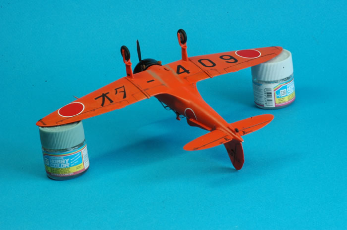
The kit provides two decal options. The first is for a Mitsubishi A5M4K Claude JP Military Dai-Nippon Teikoku Kaigun K?k? tai of the Imperial Japanese Navy Air Service, airframe # 409 in overall high-visibility orange. The second option is for a Mitsubishi A5M4-K Claude JP Military Dai-Nippon Teikoku Kaigun K?k? tai of the Imperial Japanese Navy Air Service Kasumigaura, Kokutai 106 in a dark green upper color with an orange undersurface.
The work was worth the effort. I now have an unusual airframe in my growing collection of A5M Claude’s. I look forward to building the Wingsy and Fine Molds A5M Claude’s now that this kit is finished. When the CA # 438 A5M4-K kit was first released it looked like a praying mantis or gyrocopter and did not appeal to me – it was just too odd. Now, after building it, I look forward to building another CA # 438 A5M4-K in the green over orange color scheme. I have to admit I ignored the A5M Claude family of aircraft for many years. After reading so many references I now appreciate how and why Fine Molds released so many kits for the A5M followed by the two Classic Airframes releases in 2000.
I thought the many Fine Mold A5M Claude releases were like Hasegawa’s strategy of providing new products which were mainly a re-boxing with new decals. Instead, I found Fine Molds has released most of the Claude family sub-versions (except for the A5M4-K two seater!) including the Ka-14 prototype and other significant model variants. With the recent releases by Fine Molds and Wingsy of the A4M Claude you can have some highly detailed fine looking models with less work than the kits issued released years ago.
References:
-
Air Enthusiast Vol 19 A5M Claude pages 26 to 43.
-
Japanese Fighters 1921 - 1945 No. 3 (1991)
-
Koku-Fan Famous Aircraft of the World #27 1991-3 A5M Claude
-
Maru-Mechanic # 28 5-1981 A5M Claude
-
Maru-Mechanic # 49 11-1984 A5M Claude
-
Mushroom Model Magazine Special No. 6107 Mitsubishi A5M Claude (2003)
-
Model Art # 272 Camouflage & Markings Imperial Japanese Fighters in WWII
-
Shinkigensha SKG31142 How to make the A5M & Ka-14 (2013)
Text and Images Copyright ©
2018 by Andrew Garcia
Page Created 31 August, 2018
Last Updated
1 September, 2018
Back to
HyperScale Main Page

|
Home
| What's New |
Features |
Gallery |
Reviews |
Reference |
Forum |
Search