Eduard's 1/48 scale
Supermarine Spitfire Mk.IXc
by Brett Green
|
|
Supermarine Spitfire Mk.IXc Late |

Eduard's 1/48 Supermarine Spitfire Mk.IXc Late will be
available online from Squadron
I reviewed Eduard's excellent 1/48 scale Supermarine Spitfire Mk.IXc Late Version at the end of last week.
The kit looks amazing on the sprues, but the real proof is in construction.
Would this kit be as impressive to build as it looked in the box?
Let's find out!
Before you start working on the kit, I strongly recommend that you thoroughly acquaint yourself with the instructions. If you are using any of the resin or photo-etched updates, check those instructions carefully before you start too.
As with any modelling project, taking your time and constantly test-fitting are good policies. Make sure that you are confident about the orientation and fit of parts well before you start applying glue.
That Fabulous Front Office
Eduard sent all the currently available BRASSIN and photo-etched sets along with the sample kit:
Item No.: |
Description: |
Price: |
Comments: |
648098 |
BRASSIN Spitfire Wheels – 5 Spoke |
USD$6.76 |
Block tread |
648099 |
BRASSIN Spitfire Exhaust Stacks Fishtail |
USD$6.76 |
Individual resin stacks |
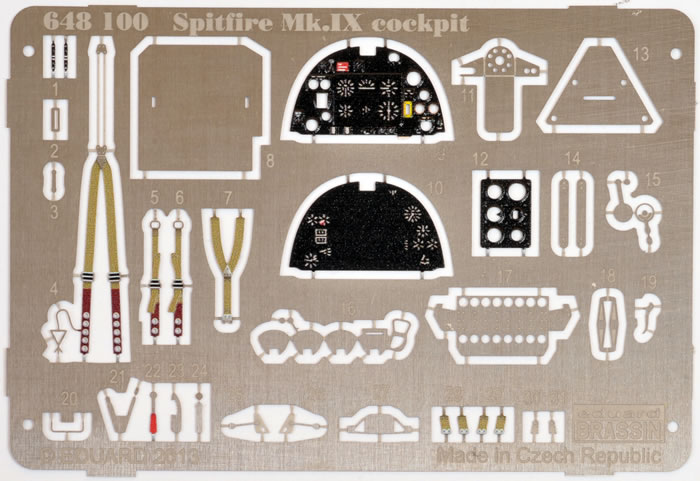
648100 |
BRASSIN Spitfire IX Cockpit |
USD$33.96 |
Resin and photo-etched parts |
49639 |
Spitfire IXc |
USD$16.96 |
Additional and replacement photo-etched detail parts |
48765 |
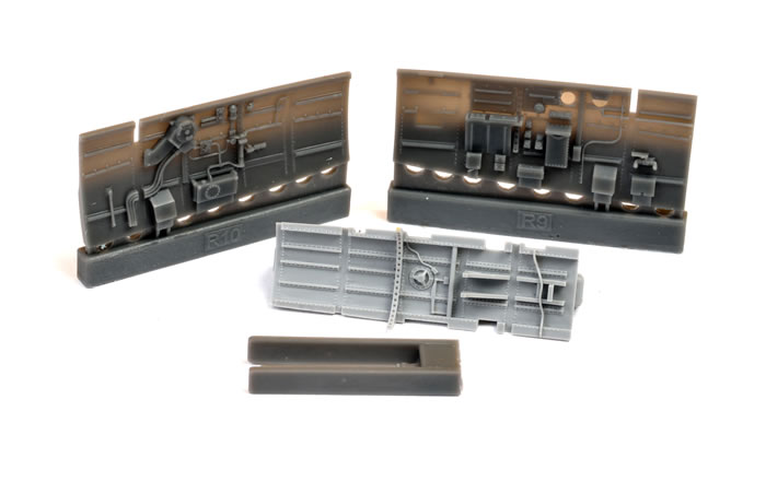
Spitfire IXc Landing Flaps |
USD$21.21 |
Landing flap and bay detail with templates. |
48766 |
Spitfire IX Surface Panels |
USD$16.96 |
Hatches, fillers, surface templates, replacement door with separate crowbar and more. |
I could not resist installing the BRASSIN cockpit (Item No. 648100), which features some incredibly fine detail on its resin parts.
I therefore spent most of the first two days working on this self-contained gem before I even cut the first plastic part from the sprue.
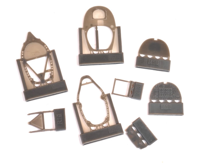
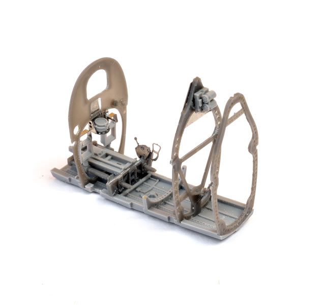
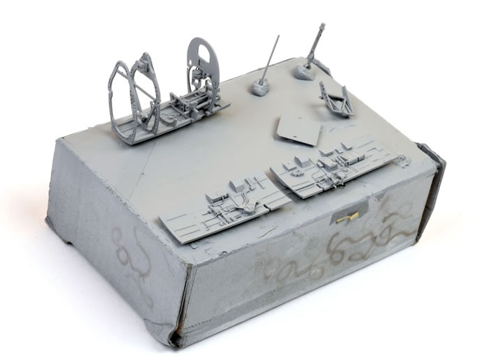
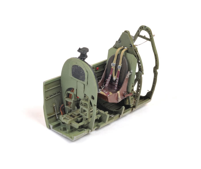
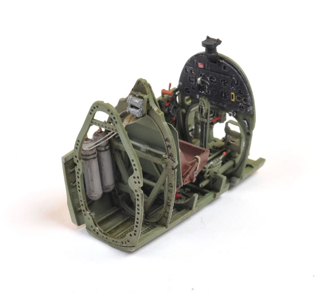
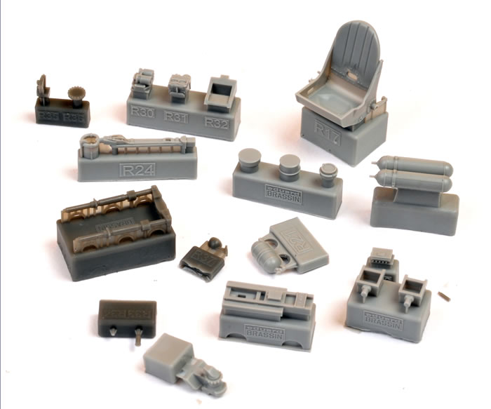
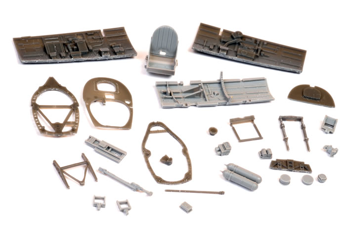
Eduard’s BRASSIN Spitfire Mk.IX cockpit comprises 33 parts in light and dark grey resin plus a pre-coloured photo-etched fret. The only kit parts used for the cockpit are the fuselage halves, and the small reinforcement strut between the tops of the two rear cockpit bulkheads.
The first step is preparation. Proper preparation of the resin parts is the most important aspect of this entire build.
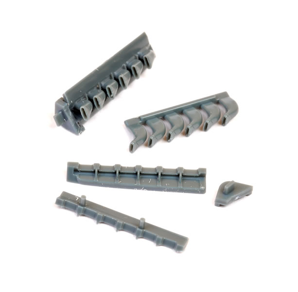
Although the casting blocks and strips and blocks are as small as could be practically expected, some time and care is required to free the parts. This is especially true of the larger parts such as the cockpit floor, the seat and the lower sidewalls.
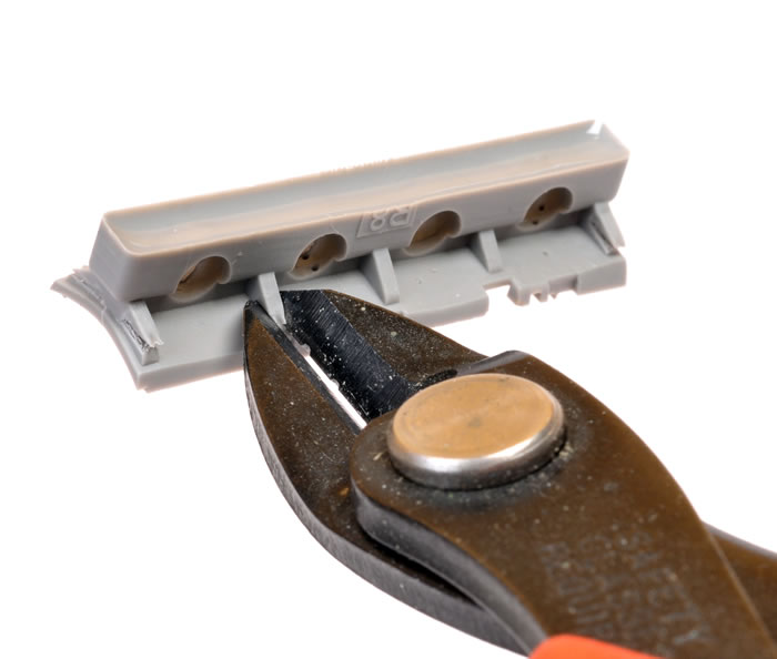
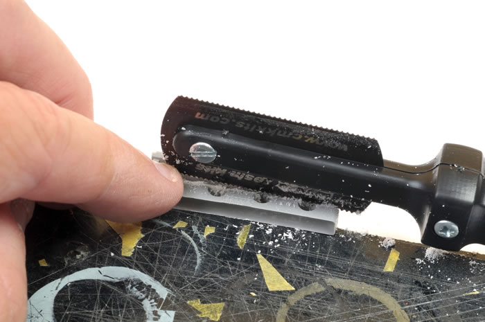
I recommend that you start by fitting a new blade to your hobby knife.
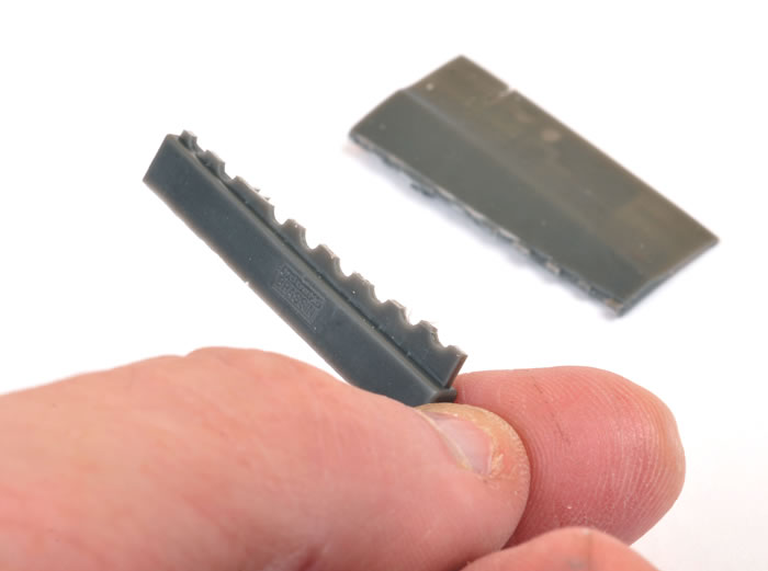
For the lower sidewalls, I scored repeatedly along the scalloped connectors joining the part to the casting block, then simply snapped the block off.
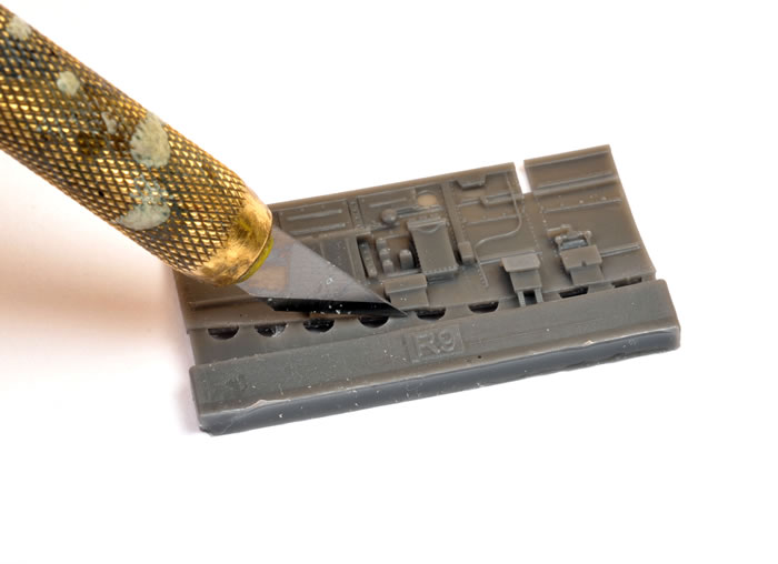
The remaining waste on the bottom of the parts were then trimmed off with my Olfa hobby knife.
I expected that I might have to break out the Dremel motor tool and a cutting wheel to deal with the long casting block underneath the cockpit floor. However, after nibbling the triangular fingers off with a pair of sprue cutters, I removed the remaining block using a razor saw. This was not as difficult or as time consuming as I had expected.
But now, a recommendation with the benefit of 20/20 hindsight… thin the bottom of the floor a little beyond the casting block at this stage. This will make it easier to fit the wing to the bottom of the fuselage when the time comes. You can either grind the bottom of the part with a motor tool, or scrape away some excess material with a hobby knife. Don't remove too much resin though, as you want to leave enough thickness to key to the bottom of the cockpit sidewalls.
I removed the seat’s casting block with a razor saw too.
If you take your time and use nice sharp tools, most of the other parts will come away from their casting blocks without much resistance.
I cut the rudder pedals off their blocks with a sharp hobby knife, but managed to slice one through diagonally. I then had to cut the remaining wedge of resin from the casting block and glue the two pieces together. You’d think I would have learned something from this experience but I managed to do exactly the same thing with the mount for the late version gunsight! Fortunately, I did not end up using that version.
In retrospect, I think it will be safer to remove these parts with a razor saw rather than a knife. It will take just a few more minutes, but will save you the ignominy of repairing your self-inflicted damage.
Also in the “do as I say and not as I did” department, you don’t need to cut out the wafer of translucent resin at the rear of Part R11. The resin mount for the instrument panel, Part R16, will lock in just fine with this membrane still in place.
The BRASSIN set offers the choice of two headrests, but you won’t need either of these for wartime Spitfire IXs. The same goes for the photo-etched flare rack in front of the seat.
Apart from these minor points, I followed the instructions. I used thick tube super glue to secure the parts except where noted otherwise in the following text.
Painting the Cockpit
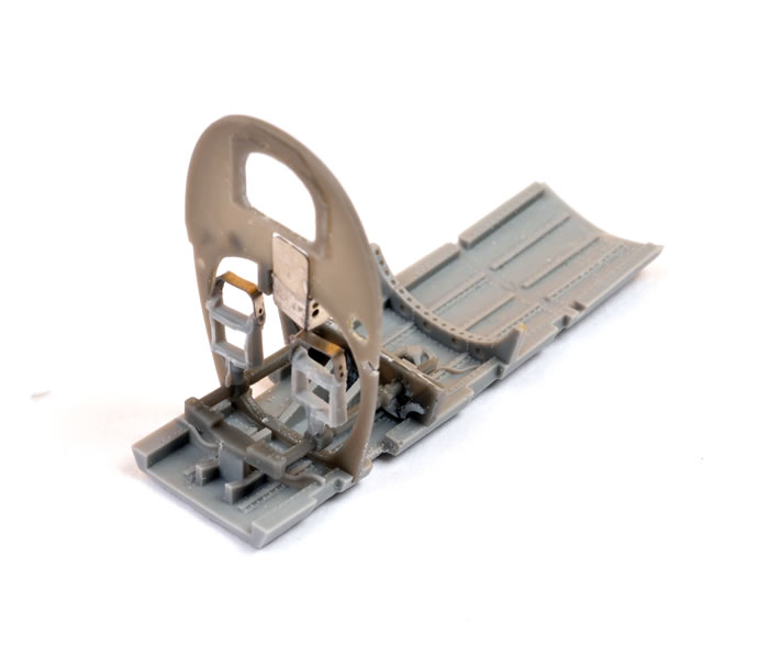
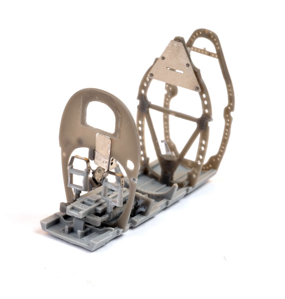
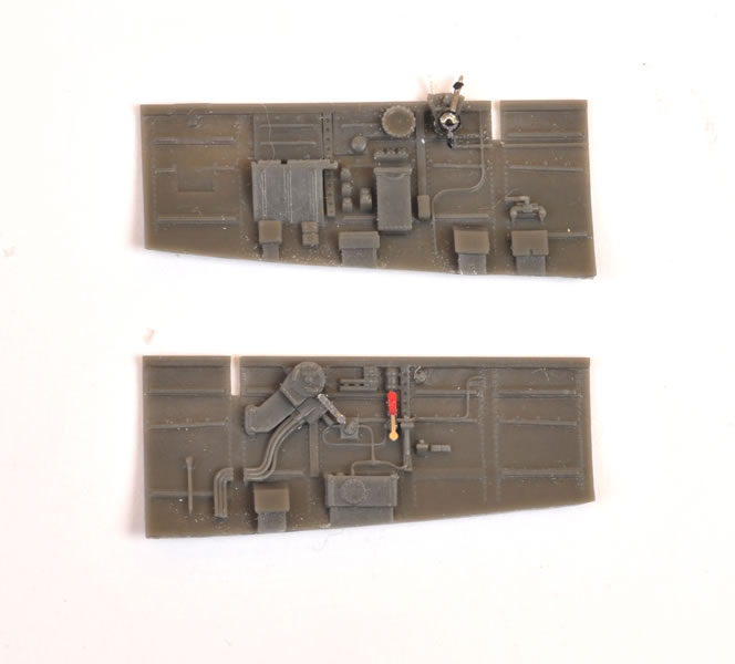
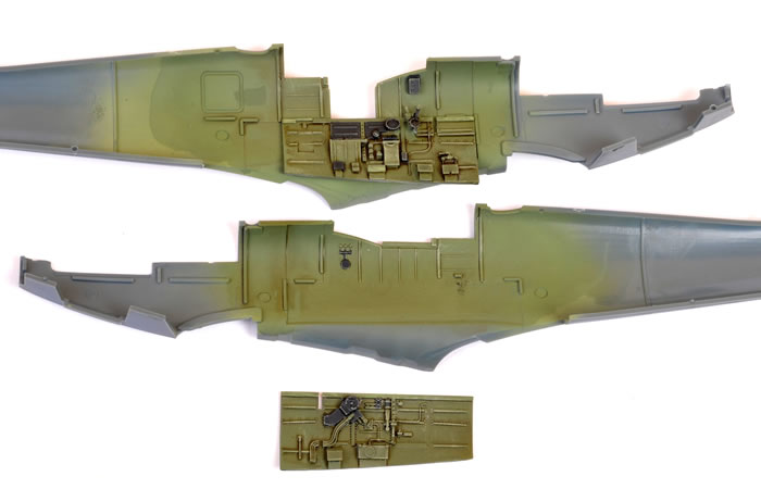
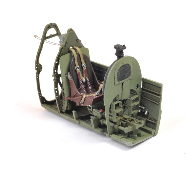
Detail parts were attached to the sidewalls and the floor - including the various bulkheads but not the seat – before each sub-assembly was painted and weathered. The seat was painted separately.
After a coat of Tamiya grey primer straight from the spray can, the cockpit sub-assemblies were airbrushed with Tamiya acrylic XF-71 Cockpit Green.
Mig Productions' 502 Abteilung oil paint, Abt.160 Engine Grease, was heavily thinned with mineral turpentine and brushed onto the painted resin parts as a filter. While this was still damp, a more selective application of AK Interactive’s Dark Brown Wash was brushed along recesses to add layers to the depth. This left a slightly darker, dirty residue in crevices and natural shadow areas.
When this shading coat had dried, I dry-brushed a mix of Tamiya Cockpit Green and J.A. Grey onto the cockpit parts.. The paint was laid off the stiff brush by wiping it on paper, then the almost dry bristles were brushed along the high points of the cockpit sub-assemblies. Next time I dry-brush, I will do so before the oil wash stage. The wash should tone down some of the more obvious marks left by the dry-brushing.
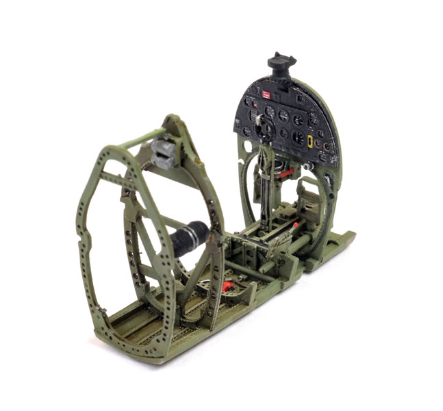
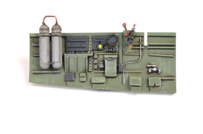
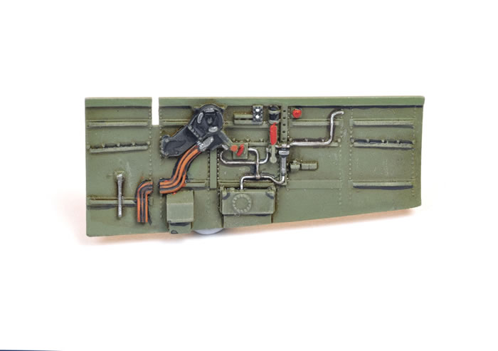
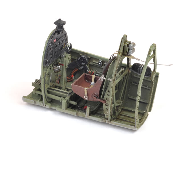
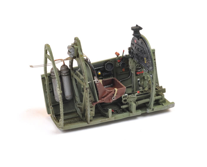
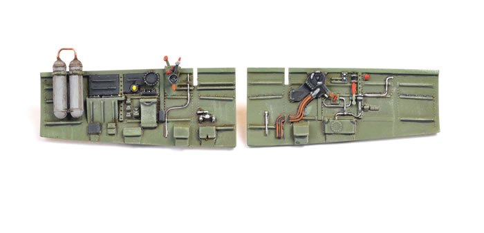
Details on the sidewalls and floor were now picked out with Vallejo acrylic paints and a fine brush. My Optivisor was very helpful for seeing all the detail parts close-up during painting.
The plumbing and wiring was painted silver and an orange-brown shade.
 Getting It Together Getting It Together
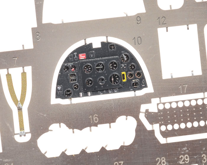
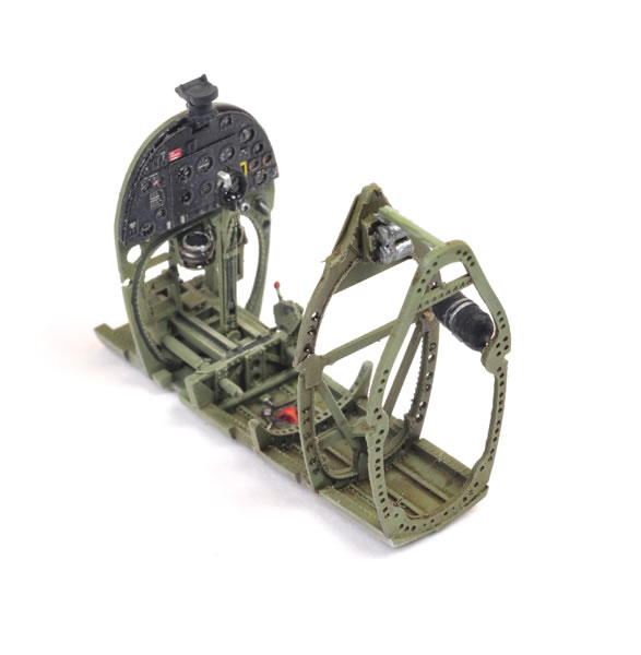
The colour photo-etched instrument panel was coated with Testor’s Model Master Flat Lacquer while the parts were still on the fret. I flat-coated the harness straps while I was at it.
Once the flat coat had dried, I brushed Future floor polish onto the dials printed on the bottom two layers of the instrument panel sandwich.
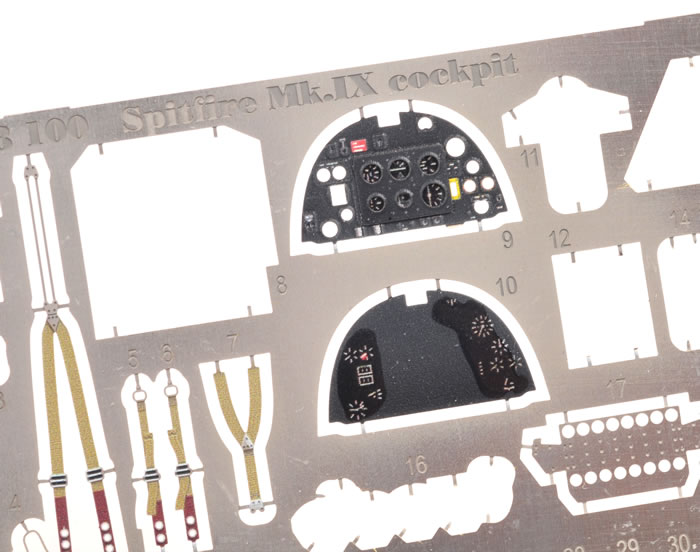
When this first coat had dried, I cut the two top layers of the panel from the fret (Parts PE 9 and 12), brushed a second coat of Future onto the dials then, while the Future was still wet, positioned the two parts on the panel’s photo-etched base (Part PE10). The Future floor polish acts as an effective glue as well as a glossy finish for the instrument dials. When everything had set, the instrument panel was glued to the bulkhead using Gator’s Grip Acrylic Glue.
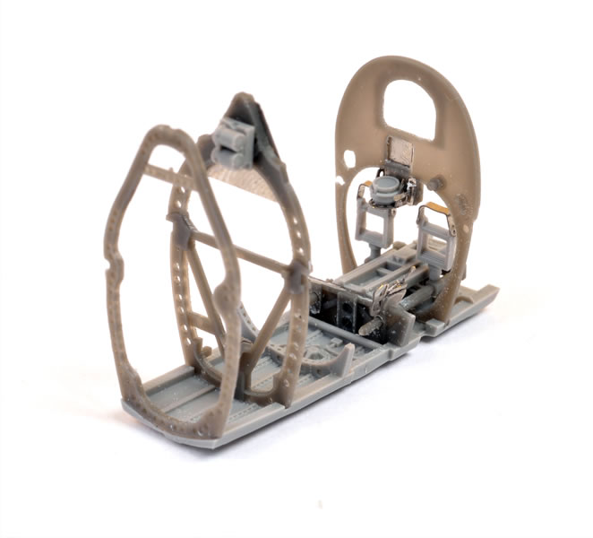
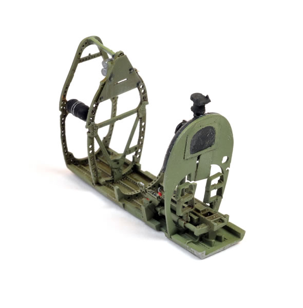
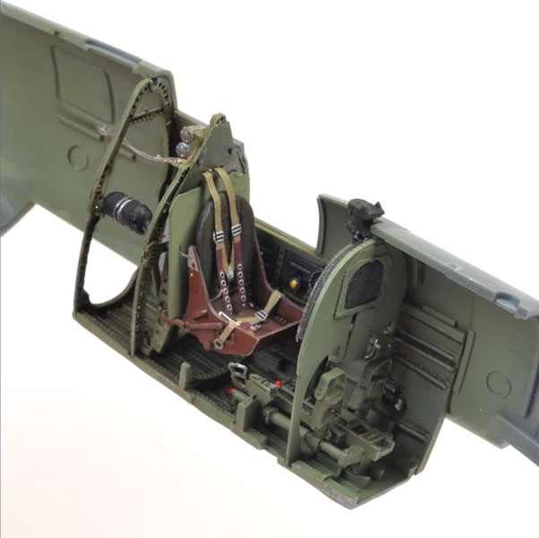
The resin seat was painted Tamiya XF-68 NATO Brown to represent the synthetic Bakelite, then the leather backrest brush-painted with Vallejo acrylics. The lap harness straps were glued in place now. Next, the photo-etched top seat mounts were pushed through the pilot’s armour and the seat was glued to the bulkhead (which had already been glued to the cockpit floor).
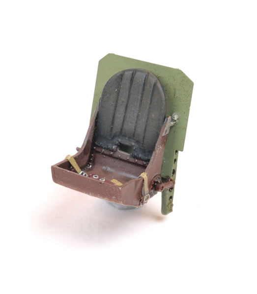
The shoulder harness was now carefully threaded through the hole near the bottom of the backrest and the slot in the top of the bulkhead, then secured to the seat with a few spots of super glue.
Not So Squeezy
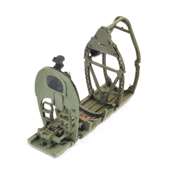
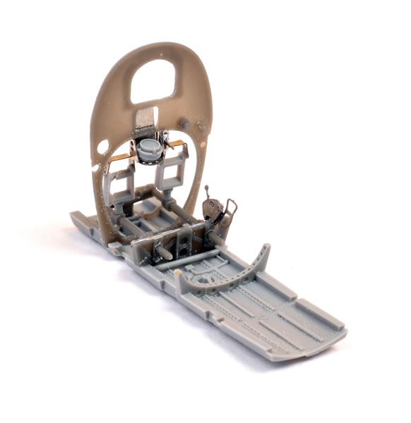
The fit of all the parts so far was extraordinarily good. Some of the resin parts were actually a snap fit, and no additional surgery had been necessary to get to this advanced stage.
The bottom of the sidewalls and the floor are keyed together precisely. The join between the sidewalls and both sides of the floor is a press fit.
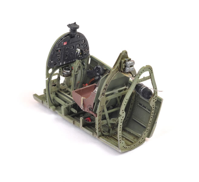
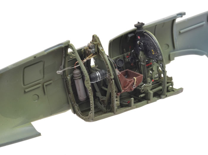
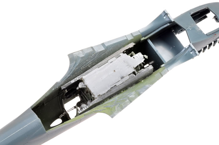
With the sidewalls pressed in place without glue, I test-fitted the entire tub between the fuselage halves. The fuselage came together without a problem aft of the cockpit, but there was a slight gap between the fuselage halves in front of the cockpit.
I dismantled the fuselage and re-examined the parts. Each cockpit sidewall has a narrow vertical slot that is intended to accommodate the bottom edge of the instrument panel. These appeared to be too narrow to fit the three layers of resin and photo-etch, so I deepened and widened the slots.
When I glued the sidewalls to the floor and the bulkheads, the edges of the instrument panel slid neatly into the slots on both sides.
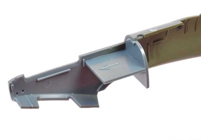
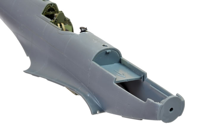
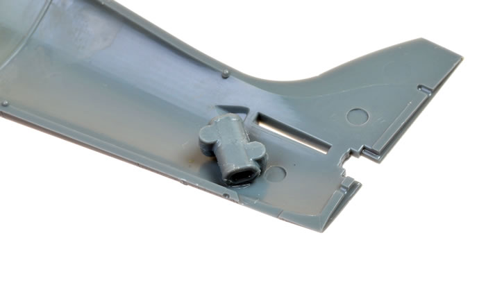
If you are using the BRASSIN cockpit, don’t get overexcited and glue the fuselage halves together just yet. Now you can return to the kit instructions, where you are advised to fit the tail gear mount and the nose reinforcements before sealing up the fuselage (the BRASSIN instructions do not illustrate these parts).
And now for the moment of truth.
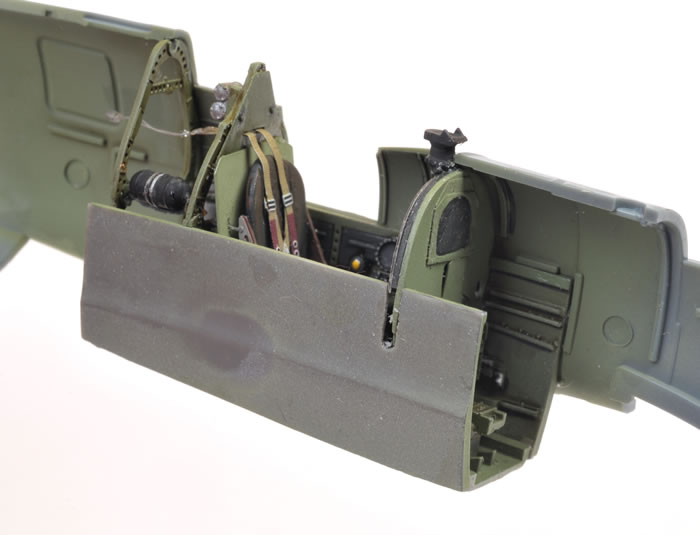
A few spots of super glue were applied to the outside of the resin cockpit sidewalls, and Revell Contacta Cement to the inside of the vertical fin. The fuselage halves were now brought together, encasing the cockpit tub. I was delighted that the parts met in the middle without any interference from the cockpit. The upper and lower join seams were brushed sparingly with Tamiya Extra Thin Liquid Cement to secure the parts.
Balance of Assembly
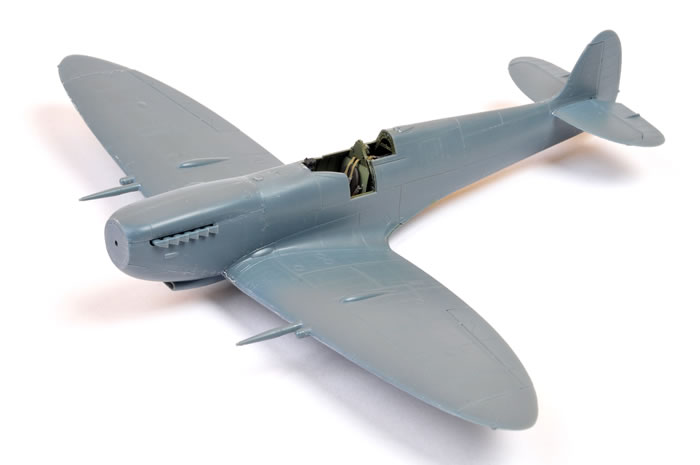
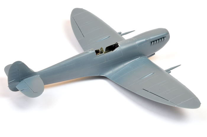
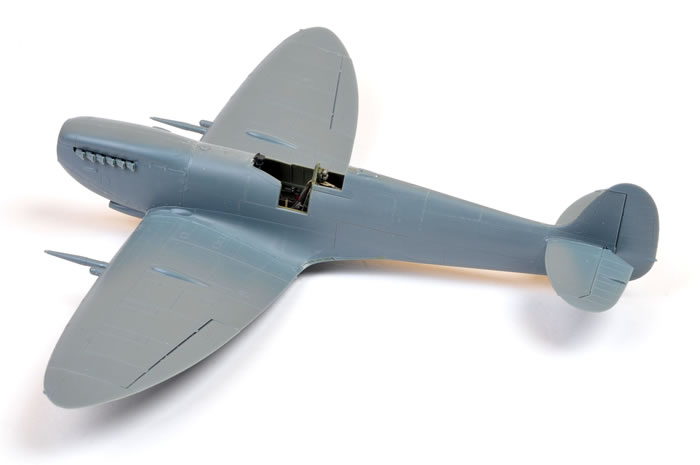
I sealed the fuselage halves around 2:00pm yesterday and I had completed basic construction of the airframe before 6:00pm on the same day.
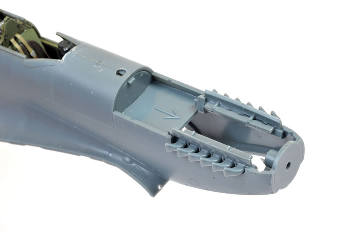
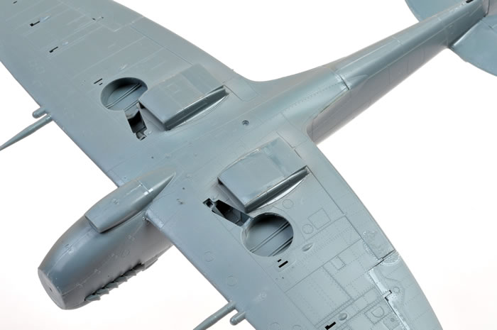
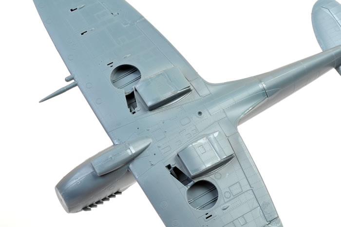
A few of the sub-assemblies look a little daunting, such as the 13-piece wing spar and wheel well sidewalls. You do need to keep careful track of the part numbers and their alignment, but everything fits perfectly.
The same may be said of the slightly baffling but ultimately very impressive exhausts and their mounts. Test fit these several times, refer to the instructions as often as you need to, and you will eventually figure it out!
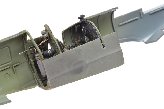
Really, the only problem I encountered was when I tried to mate the wing to the fuselage. Test-fitting revealed that the resin bottom of the cockpit floor was fouling against the plastic of the mid-wing section.
As it turned out, this was actually my fault, not the kit's.
As I suggested earlier, it is a good idea to thin the bottom of the resin floor (Part R8) before assembly. I thinned the floor after the fuselage halves were joined, but the wing still would not fit. I really went to town at this stage, aggressively scraping resin from the bottom of the floor until there was none left in some places.
This drastic reduction was, in fact, completely unnecessary.
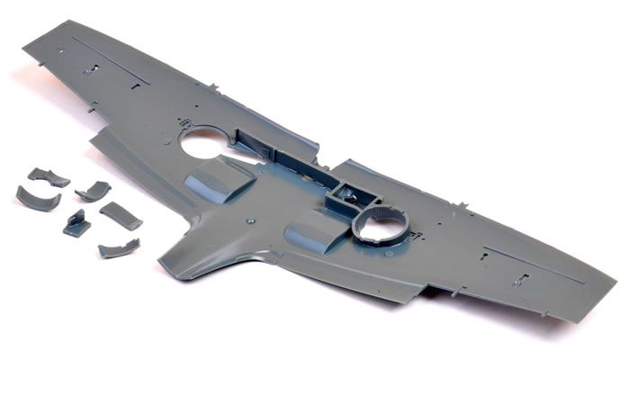
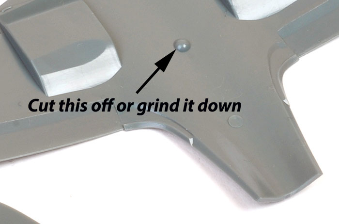
On the right side of Page 4 of the BRASSIN cockpit instructions, there is an innocent looking diagram with a small pink circle on the inside of the bottom wing marked for removal. This is the raised interior moulding for the landing light.
In my haste, I had totally missed this diagram. If I had ground this small bump off the inside of the wing, the cockpit probably would have fitted wthout any further effort. Another case of "do as I say, not as I do"!
Thanks to Jim Hatch from Scale Plastic and Rail for suggesting the source of my woes.
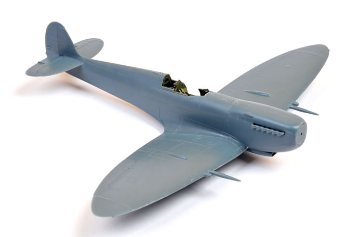
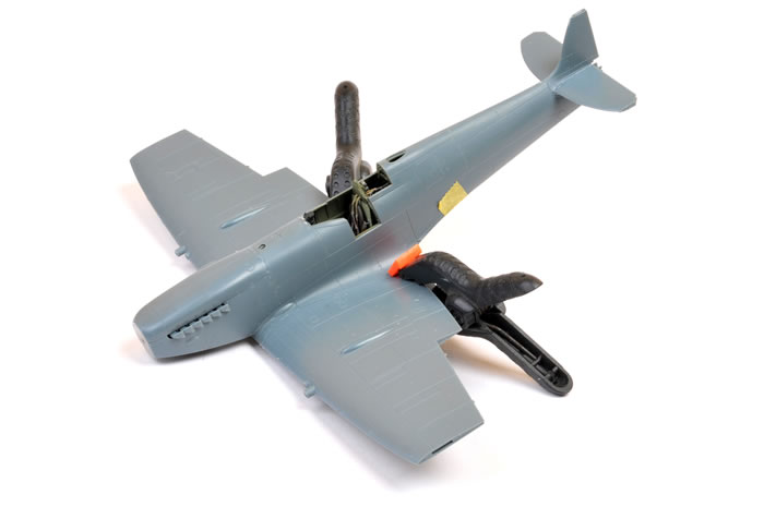
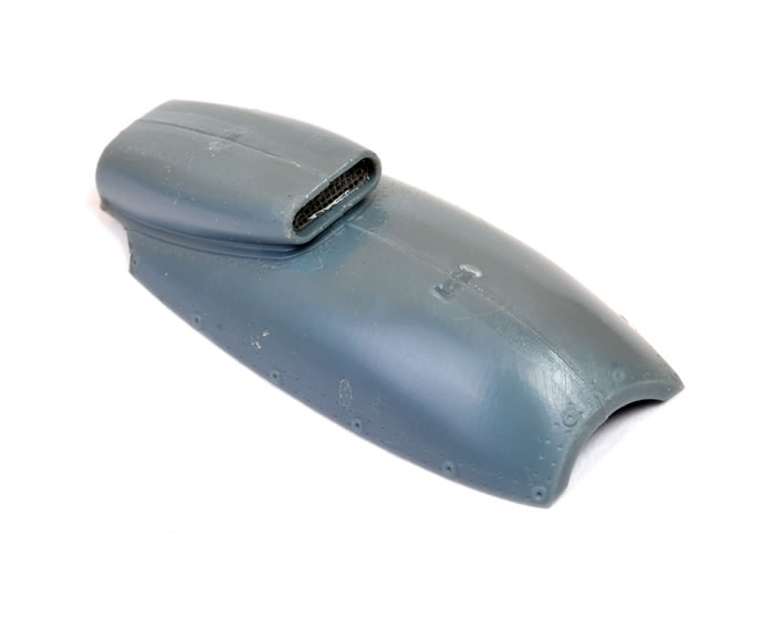
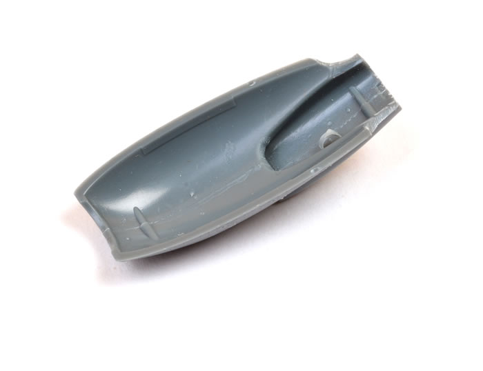
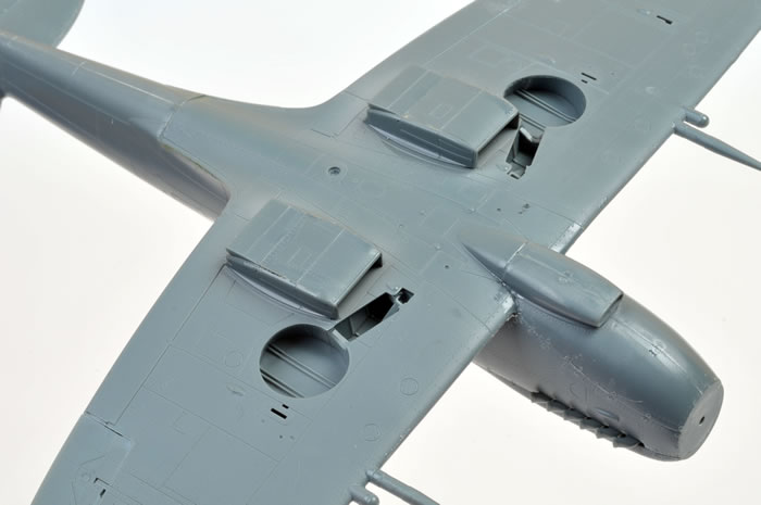
All other elements of construction – the two-piece upper cowl, the multi-part lower nose, the radiators and control surfaces – flew together.
It actually looked as if there might be a small gap between the bottom nose and one side of the engine cowling when test-fitting, but when the glue was applied it closed up nicely.
Note that there is not a spot of putty applied to the model in any of these photos. In fact, the only sanding so far has been the upper and lower fuselage seams and the leading edge of the wing.
I will assemble the undercarriage and propeller when painting is complete.
The curse has been lifted. We finally have the 1/48 scale Spitfire Mk.IX that this famous marque deserves.
The kit is accurate, well detailed, with state-of-the-art surface textures and lots of useful options.
It is also a pleasure to build; and fast too. It doesn't exactly fall together, but if you pay close attention to the instructions and test fit along the way, you shouldn't have any problems.
The BRASSIN and photo-etched upgrades are a nice touch for super-detailers. The BRASSIN cockpit really is a remarkable little model in its own right, and is a worthy enhancement for this excellent kit.
In my opinion, Eduard has delivered easily the best late mark Merlin Spitfire available in 1/48 scale.
Bravo!
Thanks to Eduard for the sample
Model, Images and Text
Copyright ©
2013 by Brett Green
Page Created 11 April, 2013
Last Updated
12 April, 2013
Back to HyperScale Main Page
|
 Home
| What's New | Features | Gallery | Reviews | Reference | Resource Guides | Forum |
Home
| What's New | Features | Gallery | Reviews | Reference | Resource Guides | Forum |