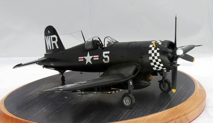
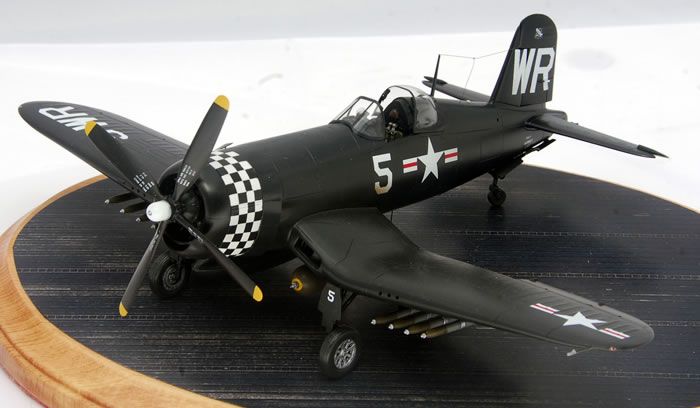
Hasegawa + ProModeler 1/48 scale
F4U-4 Corsair
by Cameron Lynch
|
|
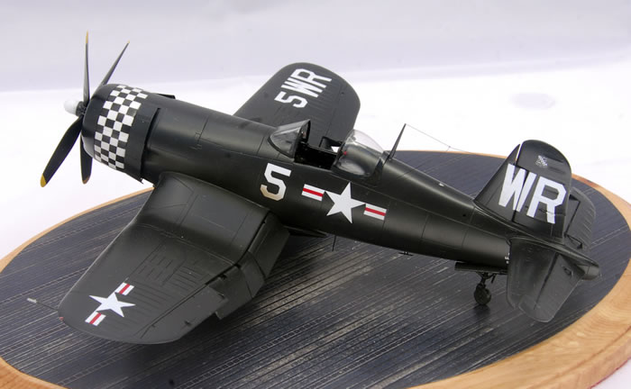
Vought F4U-4 Corsair
Major. Phillip DeLong
VMF-213, USS Bataan CVL-29 Chinnampo North Korea,
April 25, 1951 |

Hasegawa's 1/48 scale F4U-4 Corsair is available online from Squadron.com
At 0645 on April 21, 1951 Captain Phillip DeLong and his wingman Lt. Harold Daigh were jumped by a flight of North Korean Yak-9 fighters while on an interdiction mission near Chinnampo harbor in North Korea. In the ensuing combat Capt. DeLong was credited with shooting down two of the Yaks, Daigh was given credit for a third.
The F4U-4 was probably the ultimate expression of the famous Chance-Vought Corsair. Equipped with the water-injected Pratt & Whitney R-2800-18W producing 2,450hp, and a four bladed Hamilton-Standard paddle bladed propeller to make use of the new horsepower, the performance of the F4U-4 Corsair improved dramatically. Top speed increased to 448mph, and the rate of climb was an impressive 3,800 feet per minute and a higher service ceiling of 41,000 feet. Few aircraft of the time excelled the F4U-4 Corsair in its ability to deliver ordnance, with six .50 in machineguns and external pylons to carry 4,000 pounds of bombs and eight 5 inch high velocity aircraft rockets; the F4U-4 Corsair carried very nearly the same tonnage as the B-17 Flying Fortress and a salvo of its 5 inch rockets was the equivalent of a broadside from a Fletcher class destroyer. Entering service in early 1945, the first squadrons of F4U-4s supported the invasion of Okinawa and were very effective in combating the waves of Kamikazes launched by the Japanese at the invasion fleet from the southern home islands.
When the North Korean army crossed the 38th parallel into South Korea in June 1950 the F4U-4 represented the backbone of the Marine Air Groups that saw combat as part of United Nations forces during the police action. VMF-312 “Checkerboards” assigned to MAG-12 at El Toro was deployed to Korea in August 1950, where UN forces were on the brink of defeat after being pushed into a small perimeter around the port of Pusan in southeastern corner of the peninsula. VMF-312 arrived in Japan on the USS Sitkoh Bay on 18 September 1950, three days after the invasion of Inchon. VMF-312 deployed to Kimpo airfield near Seoul on 28 September before moving to Wonsan on the east coast in mid October supporting the 1st Cavalry, 7th and 24th Infantry Divisions as well as the 1st Marine Division as they pushed north toward the Chinese border. Throughout December the Checkerboards supported the 1st Marine Division fighting to escape obliteration at Chosin following the massive Chinese counterattack across the Yalu river. Returning to Japan in January, VMF-312 carrier qualified on the USS Sicily while still flying combat sorties across the Sea of Japan to strike at targets in Korea. In March the unit boarded the light carrier USS Bataan (CVL-29) which was part of Task Force 95 of the 7th Fleet. VMF-312 escorted friendly ships, blockaded enemy craft and provided armed reconnaissance between Kaesong and Chinnampo along the west coast of Korea. The Corsairs were also highly valued for their ability to provide close air support for U.S. Army and Marine ground forces in the western half of Korea.
On 21 April Captain Phillip DeLong and 1st Lieutenant Harold Daigh took advantage of a rare opportunity for air-to-air combat and scored three confirmed kills when they were jumped by four North Korean Yak fighters near Chinnampo. DeLong was credited with two Yaks, and his wingman with one. In June the Checkerboards disembarked from the USS Bataan at Itami after three months of intense combat operations, including 4,945 flight hours and 1,920 carrier landings. All of the squadron’s pilots who had deployed to Korea the previous August were relieved and returned to the United States. While most of those pilots by that time had more than 100 combat missions over Korea, the unit’s recently promoted executive officer Major DeLong led with 127 combat missions. VMF-312 was reequipped in June 1951 with F4U-4b Corsairs armed with 20mm cannon a new compliment of pilots and remained in Korea two more years. During that time the Checkerboards were based ashore at various airfields around Korea as well as aboard several US Navy carriers including the USS Bairoko, Sicily, Badoeng Strait as well as returning to the USS Bataan. On February 25 1952, VMF-312 was redesignated VMA-312, although the aircraft, pilots and mission remain unchanged. On 4 September 1952 Captain Jesse Folmar was credited with downing a Mig-15 which made the fatal mistake of pulling up in front of him after making its own firing pass on his Corsair. He quickly set the MiG ablaze with a burst of his four 20mm cannon. The Checkerboards left both Korea and their F4U-4 Corsairs behind on June 8 1953, a mere two months before the cease-fire was signed at Panmunjom.
The Kit(s)
I wanted to build the ultimate 1/48 model of the ultimate Corsair with perhaps the most attractive markings ever to grace the F4U-4…the VMF-312 Checkerboards. I started with Superscale decal sheet 48-695 which featured markings for DeLong’s Yak killing VMF-312 Corsair. The challenge was choosing the kit to put them on. When I started this project there were four choices; the vintage Monogram kit which featured toylike working features like folding wings and retracting landing gear; the old Mania/Hasegawa kit; the slightly newer Academy kit loosely based on the Hasegawa kit; and finally the CMK resin conversion for the Tamiya F4U-1. The Monogram kit with its toy features wasn’t a serious starting point. The CMK resin conversion looks impressive, and certainly Tamiya’s F4U-1 is probably the best Corsair kit available in any scale, but there are several articles/posts around the internet about using the conversion which describe it as almost unbuildable, not to mention that the conversion itself is $50 on top of the cost of the Tamiya donor kit. That left the Academy kit, which is a close copy of the Mania/Hasegawa kit with recessed panel lines. While that was attractive as it would save the time needed to rescribe the Hasegawa kit, the Academy kit has significant dimensional problems- with the fuselage being significantly too wide from the cockpit forward. It just doesn’t look right, particularly when you look at the width of the Academy kit’s windscreen and canopy. That left the venerable Mania/Hasegawa kit, which I chose to use for the project.
The more you look at the old Mania/Hasegawa kit, the more you want a new tool F4U-4, particularly when you compare it against Hasegawa’s beautiful late model Corsair kits or Tamiya’s F4U-1. While the basic dimensions and shape of the Mania/Hasegawa kit are better than the other kits, it falls short just about everywhere else. The cockpit is functionally non-existant, the engine is the wrong version of the R-2800, and the wheel wells are only a rough approximation of the real things, as are the oil cooler intakes in the wing roots and the tail wheel well. All of the little fiddly bits like the landing gear, wheels, gear doors, prop, etc. are pretty rough as well. I decided the best plan of attack would be to take the Hasegawa kit, rescribe it, and then kit-bash it with parts from the Hasegawa F4U-5 kit and some aftermarket resin. Conveniently the Hasegawa F4U-5 kit was released by Revell-Monogram as one of their ProModeler kits, and I managed to pick one up from an internet auction site for a very modest price.
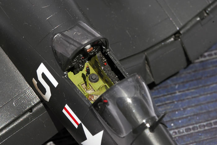
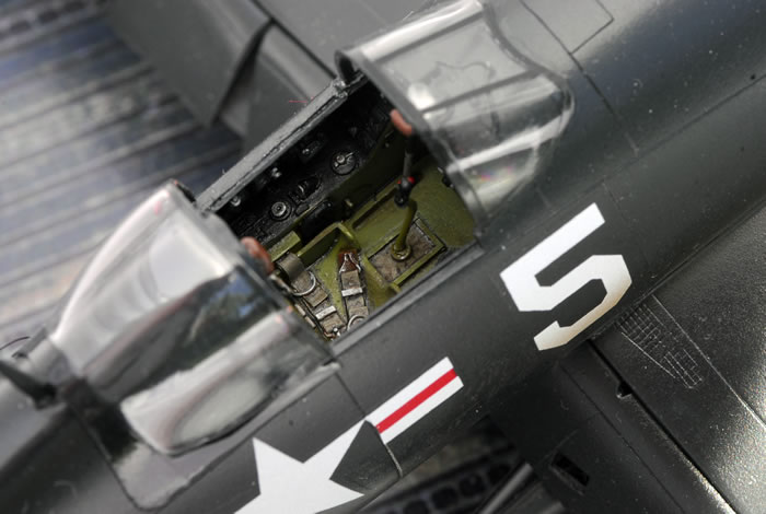
I started by rescribing the Hasegawa fuselage halves, wings and horizontal stabs using some scale plans in the AJ Press Modelmania book on the Corsair. This was accomplished using dymo label tape as a straightedge, a needle in a pin vice and the UMM Models universal scriber. Once this was accomplished I moved onto the fuselage, specifically the cockpit. Fortunately Scott Battistoni mastered a spectacular F4U-4 cockpit for True Details years ago that was designed to fit the Academy kit. With some careful grinding out of the inside of the fuselage with a Dremel motor tool and some careful sanding of the resin tub it fit well, a little more work was needed to make the rear bulkead fit the narrower Hasegawa fuselage. Some painting and a wash and the cockpit was ready to install when I closed up the fuselage.
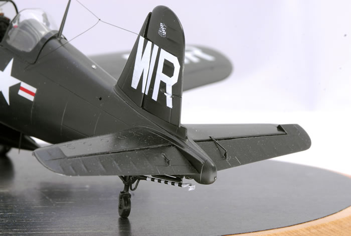
The next task on the fuselage was to scratch build the tail wheel well. I was going to substitute the hasegawa tail strut/wheel/arrestor hook, and realized that I would also need to open up and scratch the wheel well. The ProModeler tailwheel is great except for the poorly molded mooring point that I replaced with some appropriately sized wire bent to shape in a jig. I then scratched out the interior of the tail wheel well using Evergreen sheet for the forward and upper bulkheads and strip for the longerons and stringers. I was careful constructing the well so that when the time came I could easily install the tail gear and arrestor hook after the model was assembled and painted. I then closed up the fuselage, using some strip to reinforce the back of the long seam on top of the nose.
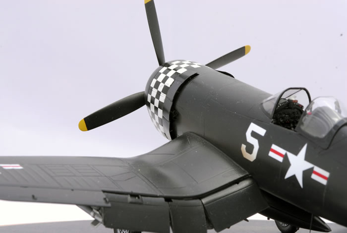
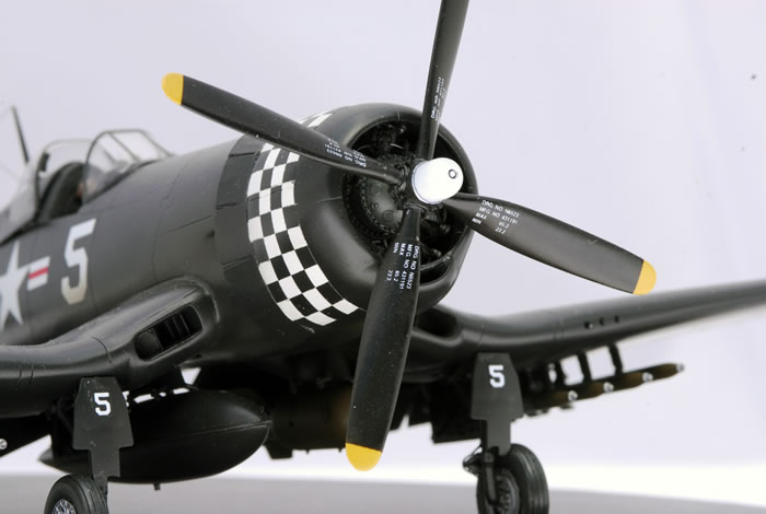
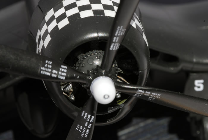
The next task was to correct one of the major accuracy problems of the old Hasegawa kit, the wrong Pratt & Whitney R-2800 engine. The Hasegawa kit has a very “soft” representation of the R-2800 “B” series engine which had the cast magnesium gear reduction housing on the front. This is similar to the engine that was found on the early F4U-1 Corsair, P-47D Thunderbolt and F6F Hellcat. The F4U-4 was equipped with the late “C” series R-2800-18W engine that had the two-piece round gear reduction housing ringed with bolts. This is the engine that you would find on the P-47M/N Thunderbolt, F7F Tigercat and F8F Bearcat. I didn’t plan on opening up the engine cowl so I started with the cylinder row parts from the Hasegawa/ProModeler F4U-5 which is one of the nicest C series double wasps in styrene. I added some cast resin magnetos and prop governor and then used fine lead solder to create the oil return lines and the correct Pratt & Whitney “cast” ignition harness. I also had collected the old Verlinden F4U-4 upgrade set which has a nice set of photo etched cowl flaps, so I opened up the cowl flaps before I added a sheet styrene firewall. I then built a jig out of styrene to ensure that the engine would be properly centered in the front cowling before mounting the engine. With the engine mounted correctly, I opened up the carburetor intake on the cowl chin and installed some fine brass mesh for the intake screen before installing the leading edge of the cowling.
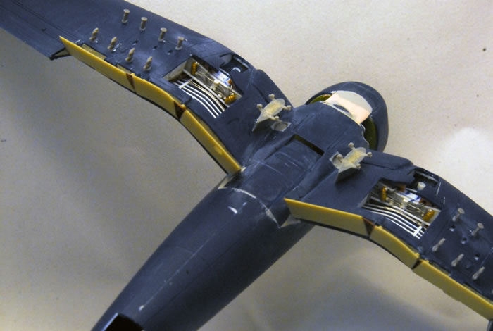
With the basic fuselage complete, I moved on to what I knew would be the majority of the work on this build. I wanted to replace the wheel wells, drop the flaps, replace the oil coolers in the leading edge. I also needed add the correct launch bridle hooks and accurate HVAR rails and bomb pylons. I planned to use a spare set of Aires resin wheel wells for the Tamiya F4U-1 kit, so I started by removing the flaps and grinding out the main wheel wells. I knew that getting the Aires set to fit the Hasegawa F4U-4 would be a challenge so I thinned the plastic until it was translucent when held up to a light and then did the same to the resin wheel wells, carefully working on it a couple of weeks. The Aires parts were just too thick to fit in the Hasegawa wings, a fact that I realized when I ended up grinding and sanding completely through the tops of the wings and they still wouldn’t fit. Frustrated, I put the kit up on the shelf of doom for a couple of months until I worked up the emotional energy to start over on the wings. In the meantime I kept my eye open for another cheap Hasegawa F4U-4 kit that I could obtain for an extra set of wings.
Realizing I would have no alternative but to completely scratch build new wheel wells, I spent more than a little bit of time looking at photos, drawings, other kits so that I fully understood the geometry of the Corsair wheel well structure before I started. I took a drill and using the existing socket for the locating pin for the landing gear as a starting point, drilled through the upper surface of the wing and inserted a length of styrene rod that would locate the landing gear struts when I was finished. Then I used my Dremel motor tool to grind out the old wheel wells from both halves of my replacement set of wings, this left a smooth surface with which to work. The lower wing bottoms now featured two holes where the wheel wells once were. The first thing I did was scratch the main wing spar structure that is at the leading edge of the main wheel well out of styrene strip and a little renshape. Then using sheet styrene, a pair of dividers and a contour gauge, I made the inboard, outboard and rear bulkheads. Then I finished boxing in the area in front of the spar where the struts mount. I had already decided to use the main gear struts from the ProModeler kit, and I constantly kept fitting them in place and taping the wings together to ensure that everything fit correctly and the alignment was in the ballpark.
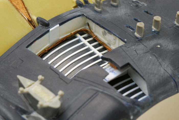
Once the wells were boxed in, I then used styrene strip and structural shapes to add the appropriate detail to the wells. Then I needed to replicate the hydraulic valves and actuators found on the aft side of the main spar that actuate the landing gear as well as the gear doors. I raided a stash of brass model railroad parts for some of the actuators, and scratch built the rest with styrene rod. The last thing needed in the wheel wells were all of the electrical cables and hydraulic lines. I used a mix of fine copper wire and fine lead solder. It was a little depressing to know that all of the detail would be painted gloss sea blue and would largely disappear into a dark blue hole.
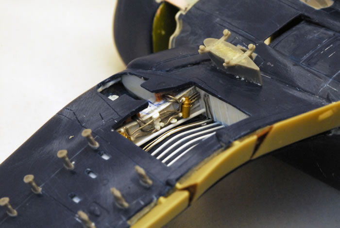
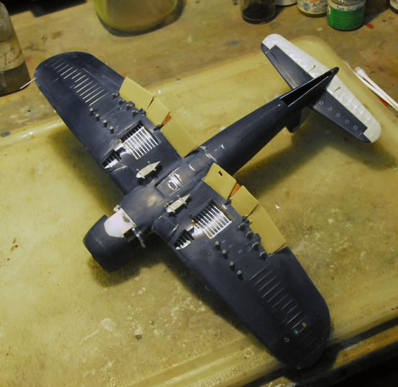
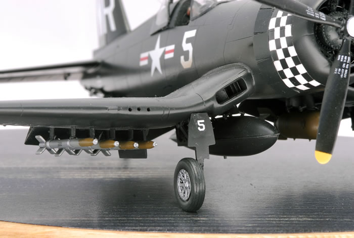
There were some more details to sort out on the wings. The first was removing the flaps with a razor saw. The second was opening up the machinegun ejector ports and boxing them in so they had visual depth. I had a lot of work to do on the oil cooler intakes. The original kit oil coolers are basically just holes in the wing with a sad little 2d plastic representation of the mesh oil cooler front without any of the ducting or vanes you see on the real item. I started out scratching my own oil cooler with strip and fine brash mess, and then I realized that with a little surgery the intakes from the ProModeler kit would fit and would be a 200% improvement without the hours of scratching. I also opened up the fuselage vent for the engine accessory bay. I took the opportunity to correct the catapult launch hooks by removing the launch hooks from the ProModeler kit with a razor saw, and then gluing them into some appropriately sized holes cut in the Hasegawa wings. The last thing I did before closing up the wings was using some plans and a divider to drill all of the mounting holes for the ProModeler rocket stubs and bomb pylons in the correct locations.
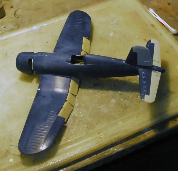
With the wings together and glued to the fuselage I felt like I was making some progress. I had some more details on the wings to finish up before tackling the wing flaps. I replaced the wingtip position lights with polished clear acrylic rod with a tamiya clear red/green “bulb” drilled into the back. I also drilled out the red/green/amber recognition lights under the port wingtip and installed MV lenses. One detail that made a big difference was drilling out the machine gun ports on the leading edge and fairing in short lengths of styrene tubing, making the ports perfectly round and eliminating a challenging seam problem.
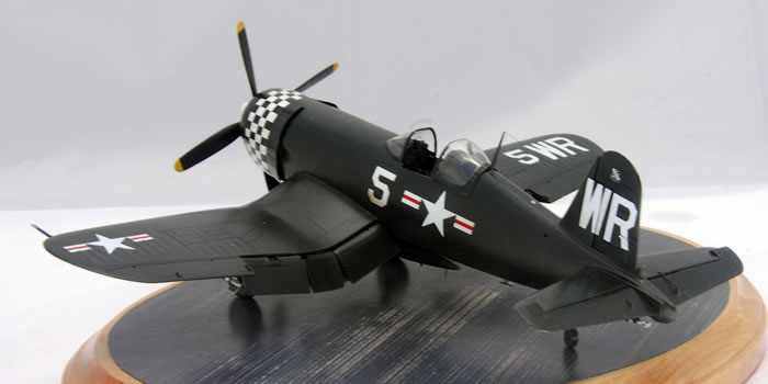
While I hadn’t planned on folding the wings, I did want to drop the flaps. They give the Corsair a very characteristic look from the rear quarter and accentuate the Corsair’s gull wing. As part of the Verlinden upgrade that I had been cherry picking parts from was a nice looking set of resin flaps. The Verlinden set was for the Academy kit, whose wings are interchangeable with the Hasegawa kits, so I hoped they would fit. But my luck wasn’t that good. First I used epoxy putty to fill the holes left in the wing and the wing root of the fuselage by the removal of the kit flaps. While the epoxy was still setting up, I sculpted the putty into the appropriate “S” contour aft of the rear wing spar in front of the flaps. With the gap finished, I then installed the photoetched pieces that detail the end on each of the six parts that make up the flaps. I was a bit chagrined to see that the airfoil shape of the Verlinden etch pieces didn’t match those of the resin flap parts…a glimpse of what was to come. When I went to install the flaps, they were collectively wider than the space they had to fit into. Carefully removing the etch pieces and then repeatedly sanding and test fitting the flaps until they fit correctly.
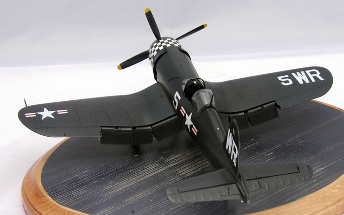
Now I was in the home stretch and I was starting to feel good about the kit. I painted all of the little parts that remained, the ProModeler prop, the landing gear, the Ultracast mainwheels, the tailwheel and striped tailhook, and most obviously the ordnance. Looking through reference photos of F4U-4s during carrier operations off of Korea that showed some interesting asymmetrical weapons loadouts that I replicated on my model. The drop tank and HVARs came from the ProModeler kit while the resin bomb came from an old True Details set.
Now was time for paint and decals. By and large an overall gloss sea blue paint scheme is a no-brainer, but this one posed a little bit of a challenge for the checkerboard on the nose. Although the Superscale decal sheet came with a checkerboard decal I was unconvinced that it would fit correctly, so I resolved to paint the checkerboard. I used a technique that Bob Steinbrunn did an article about in FineScale Modeler about 15 years ago on a P-47. I used strips of Tamiya tape cut to the appropriate length around the front of the cowl and placed it so that one end was at the juncture of the grid on a piece of graph paper. I knew the rough size and number of the checks, so I counted off the appropriate number of grid lines and stuck the other end at that juncture. By using a fine mechanical pencil I could then tick off lines on the masking tape where the grid touched it...evenly distributing the appropriate number of blue and white checks around the circumference of the cowling. I also did this across the depth of the cowl in about five points around the cowling and then did the same thing for the back of the cowl as well as where the checks would meet in the middle. I then painted the cowl white and masked it with bare metal foil. I then took the strips that I had marked and laid them over the bare metal foil and using a flexible straightedge and a fresh scalpel cut the foil into a checkerboard pattern using the markings on the tamiya tape as a guide. I then used a pair of tweezers to pull off alternating squares of bare metal foil to expose the white underneath. I masked the cockpit, engine and the already installed position lights and was ready to paint. I thinned up some Gunze Lacquer gloss sea blue with a little lacquer thinner and some Gunze self leveling thinner to retard it a little.
After I was finished I removed the rest of the bare metal foil on the cowl, exposing the white checkerboard pattern. Now on the downhill run, I broke out the Micro Set and decaled the aircraft using a couple of Superscale sheets and then I very lightly weathered the aircraft to reflect contemporary photos of shipboard F4U-4 corsairs.
Now I had to finish the model off with the myriad of little details that always seem to drag on. I added an acetate reflecting lens to the resin gunsight and installed it, along with the resin armament boxes on the instrument coaming. I ran some fine gauge wire painted black for the armament boxes and then installed the kit windscreen that had been framed with painted decal strips and given a coat of future. Using scale plans I built a jig and installed the landing gear and tail gear using 5 minute epoxy to give me a little bit of work time to ensure that the alignment was perfect. Then I installed the painted Ultracast wheels and the various gear doors sourced from the ProModeler kit that had been pre-painted. I installed a clear position light on top of the fuselage and another at the tail. Fine brass wire was used for the trim tab actuators. An insect pin was used for the antenna under the fuselage, and then I used a resistance solder to jig and solder a radar altimeter aerial that also went under the fuselage. Just as I was ready to put it on the shelf I had to install the Verlinden cowl flaps…which didn’t fit. Nor could I make them fit, so I ended up using thin gauge aluminum sheet to replicate each of the cowl flaps. After painting the new cowl flaps, I attached them to the model which got a final coat of Alclad Light Sheen clear to even everything out.
As a postscript, the new Hobby Boss kit was released about the time I was ready to paint the model. By that point I had invested enough time and treasure that I decided to carry the project on to completion. After reading some of the reviews of the Hobby Boss kit, I still think that the definitive F4U-4 in 1/48 has yet to be released. I’m still satisfied with mine.
Text and Images Copyright ©
2012 by Jon Bryon
Page Created 7 September, 2012
Last Updated
17 September, 2012
Back to
HyperScale Main Page

|
 Home
| What's New |
Features |
Gallery |
Reviews |
Reference |
Forum |
Search
Home
| What's New |
Features |
Gallery |
Reviews |
Reference |
Forum |
Search