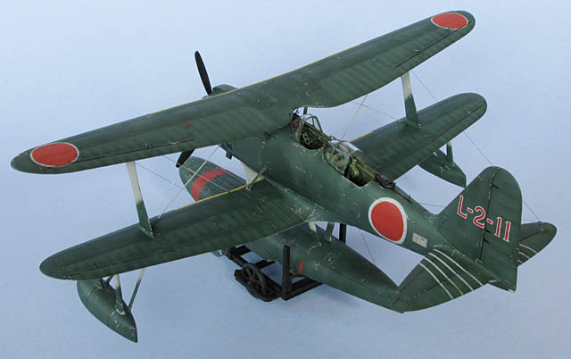
Washing Machine Charlie
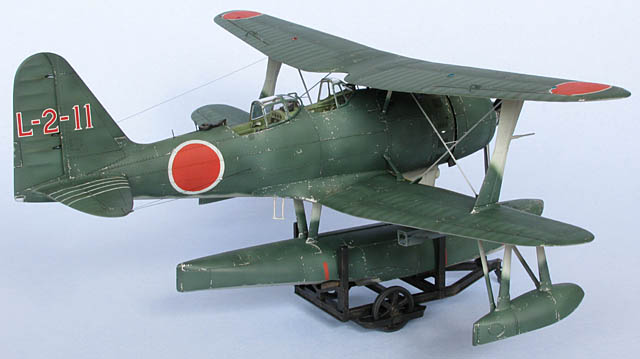
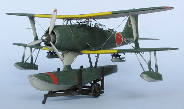
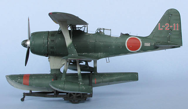
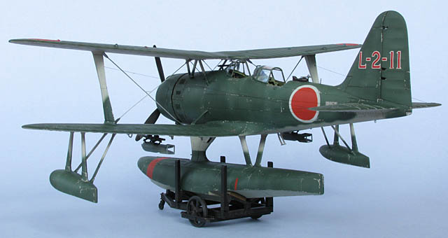
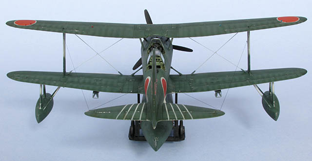
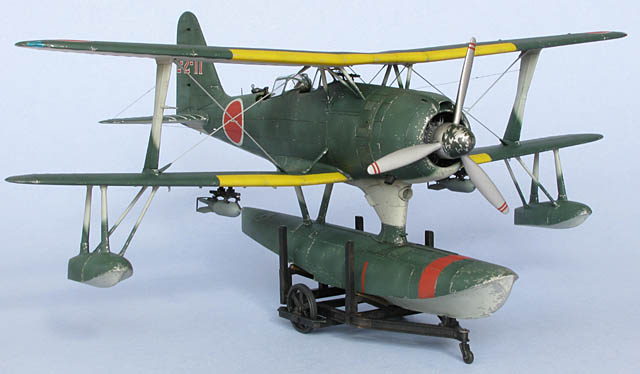
Hasegawa's 1/48 scale Mitsubishi F1M2 Type 0 Observation Seaplane (Pete)
by
Bruce Salmon
|
Mitsubishi F1M2 Type 0 Observation Seaplane (Pete) |

Hasegawa's 1/48 scale F1M2 is available online from Squadron.com
The Pete has been a favourite of mine for a long time – hybridising biplanes with floatplanes can only be a good thing. In fact until recently I had the old 1/50 scale Tamiya kit to which I had made extensive exterior renovations. Not only had I acquired a Val and a Zero to kit-bash an interior and engine/ propeller for it but I also scratchbuilt a catapult for it to sit on. When the new Hasegawa Pete appeared on the scene I ditched the Tamiya version, sold it for a pittance, but kept the cat. On a darker note – don’t store your plastic in the roof - it gets hot up there. My cat is now a yellowed and twisted wreck!
In this article I will go through each step in the instruction book and give you the low-down on this kit’s good and bad points and the pitfalls you need to look out for. Having said that; be aware that biplanes always require a bit more forethought to make sure that you don’t build yourself into a corner. This means that the kit’s instruction steps are not in an order that should be followed if you want to get the best trouble-free results.
Aftermarket Products Used:
Hasegawa (QG32) Etching Parts
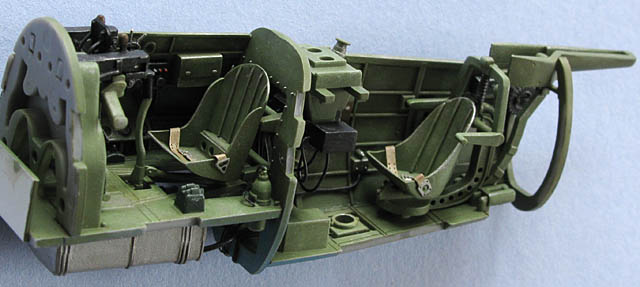
STEP 1
Here we are in the cockpit. It’s actually very nice straight from the box – certainly a vast improvement on previous kits. But what’s this I see?... cushions on seats… no, no, no – new seats had to be scratchbuilt and seatbelts obtained from an Eduard Japanese seatbelt set to compliment them. The kit has no seatbelts as decals nor are there any in the etch set – a big disappointment.
Throttle quadrants also had to be improved – I used left over PE parts from the Eduard Kate set (this set has proved useful to me on more than one occasion). A few wires added here and there will increase the realism (use the Eduard F1M 49445 instruction sheet as a guide). Most of the Eduard set for the cockpit is superfluous, not visible and therefore an unwarranted expense.
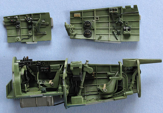
Part N3 also needs fixing as it is just badly moulded. I made a new one by copying a photo I found of a similar compass type instrument attached to the NASM Aichi Seiran.
The Hasegawa etch for the instrument panels is just plain annoying. Firstly being made of stainless steel you will break bits off on every other one you bend. The backing has got badly etched dials that you have to put a decal over (it won’t conform to the ridges so why bother) then you have to fold it perfectly so that the dials are central in the faces on the top half. The Eduard set is way better in this respect. I painted my dials and filled the face with loads of Future.
If I was to do it again I’d just snap off the back face and instead apply the decals onto 10 thou card then glue it to the front face and once dry sand the edges to shape. …or you could just thin out the kit parts. Also if you are using the Hasegawa PE you won’t be able to follow their order of construction or you will have problems – make sure you dry-fit everything first.
STEP 2
Glue the cockpit tub to one fuselage half while at the same time dry-fitting the other half. This is necessary to ensure that the tub is located centrally. Once the halves are glued together then add the cockpit coaming (part G1). This part is open at the front end and fairly flimsy so to make sure it will fit properly you will need to dry-fit the windscreen (part R1) before the glue sets. As an aside my fuselage (sprue A) was made from some sort of horribly soft plastic when compared to the other sprues.
STEP 3/4
Glue the wings and horizontal stabilizers together. These have a very thick trailing edge which took days of sanding to thin down to a reasonable profile. Then attach the lower wings and the stabilizers. Leave the clear parts off until last when painting is complete.
STEP 5
Now pay particular attention to this order of construction for a hassle and stress free time. For this exercise I am assuming that you are using the Hasegawa PE.
Attach the little fuselage struts E15 and E16 – what they’re too long you say… well then cut off the locating pins, sand them shorter then glue them on (you may want to fill the corresponding locating holes too).
Next dry-fit the plastic parts and then leave them alone until later when the rest of the model has been fully painted and the floats are on. The process will go like this…
Drill deep holes in the fuselage at the correct angle to accommodate the PE parts. Paint all plastic struts and PE parts separately. Glue wing struts to lower wings and cabane struts to fuselage – dry-fit upper wing to ensure they line up properly. Once dry add the PE wires to the cabane struts then glue on the on the front windshield and sighting periscope before attaching the upper wing.
STEP 6
Dry-fit the outrigger floats to the lower wing and glue the angled struts (parts E11, 12, 17, 18) to the floats but not to the wing. They are a sloppy fit. Once dry bog any gaps, sand and put them aside for painting. The exhaust pipes can also be painted and put aside at this stage.
Later on when the lower wings have been painted you can attach the floats and easily touch up any boo-boos where they join.
STEP 7
The bombs PE parts are a nightmare to assemble and it’s pretty much impossible to achieve perfect results. It might be a good idea to make the fin support (MA22) first and then glue the fins to it. Then you can fit the bomb to the finished assembly. It’s all very tricky no matter how you want to attack it – good luck. And of course once completed leave them off until the end of the build. You could always just biff them out and save the headache.
STEP 8
The main float is nice but make sure you use all of that 20g weight up front (more is better). I would cut off the locating clip at the bottom of the fuselage connection so that you can take them apart again. You can glue the main float on now or later.
STEP 9
The sighting periscope (L18) sits up too high when inserted into the hole in the front windscreen - some fixing juju is needed. The rear canopy (N7) is ridiculously thick, don’t be tempted to use it - throw it away! My canopies appear to have been taken out of the moulds before they had cooled sufficiently leaving drag marks and flash. They needed hours of sanding and polishing.
Next comes an adventure with bracing wires. I started with folding and gluing on the end pieces (MA28-34) – many of them snapped off but eventually I succeeded in getting them all on. I filled the edges with super glue and sanded them smooth. I did a test fit and found that they were too long and the bridging bit between each wire caused them to warp - so I cut them in two.
Next I snapped off the upper rounded tabs and that solved the length issue. They were then painted and glued in place. A bridging wire was then added using thin brass wire - a tricky task. I didn’t add the aerial wire (MA25, 26) as I thought it was too thick – I used stretched sprue once everything else was finished.
Tip of the day: When you glue in PE bracing wire or even nylon for that matter you should do it on a day when temperatures are mild. If you do it on a hot day you will notice that when temperatures cool down the kit plastic will shrink slightly and you will end up with saggy wire syndrome.
STEP 10
The propeller is a step back into the dark ages of modelling as Hasegawa has given it raised detail for the anti split-your–head-open-on-the-blade-tip stripes (no decal here either). The propeller balance weights (A10, 11) can be left off as you won’t see them after the spinner is attached.
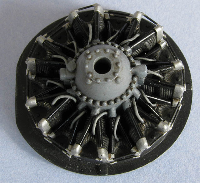
Now for some bigger problems… The engine will not fit into the cowl centrally as there are blocks that hang down from the gun tubes that prevent it lining up. Get out your dremel for this one.
STEP 11
Once that is solved you will find that when you attach the cowl / engine assembly to the front of the fuselage there is a horrible big gap between the cowl and fuselage. You will need to dremel out the back of the engine so it will fit closer. You certainly won’t find this kit in an OOB competition!
STEP 12
The trolley – no problems here except to fill the ejector pin marks.
PAINTING
All Enamels…
Interior: 5 – Tamiya XF71 Japanese Interior Green / 1 – Tamiya XF62 Olive Drab / 2 – Tamiya XF57 Buff
Upper Surface: 1 – Tamiya XF11 JN Green / 2 – XF70 Dark Green 2 (IJN) straight from the bottles. Post shaded by adding 1 – Humbrol 226 Interior Green / 1 – Tamiya XF2 White then just increasing the amount of white.
Lower Surface: 9 – Tamiya XF12 JN Grey / 1 – Tamiya XF2 White
Hinomarus: 15 – Tamiya XF7 Flat Red / 1 – Tamiya XF9 Hull Red
Leading edge stripes: 9 – Tamiya XF3 Yellow / 1 – Humbrol 82 Orange Lining
DECALS
The only decals I used were the tail codes. While they are the new variety with fully white whites they are a never the less a strange animal. They adhere well with no silvering and are nicely opaque.
However, they will not settle down into panel lines even after numerous applications of Mr Mark Softer. They did however wrinkle up as usual.
While this kit is certainly better fitting more accurate and refined than the older Tamiya version it is not without its problems. Hasegawa has made some really poor engineering decisions / mistakes and for such a modern kit this is inexcusable. The Hasegawa PE set is only really useful for the bracing wires but then even the Eduard set is hugely padded out with obscure and unnecessary parts. Both companies really need to rethink their PE sets for this model. You may think that I’m being a bit pedantic about some of these things but I expect things to improve over time – most of these issues should just not happen nowadays.
Though a bit of a mixed bag I do like the kit and you can turn out a really great looking aircraft with a bit of forethought and extra elbow grease.
Model, Images and
Text Copyright © 2009 by Bruce Salmon
Page Created 6 October, 2009
Last Updated
6 October, 2009
Back to HyperScale
Main Page

|
 Home
| What's New |
Features |
Gallery |
Reviews |
Reference |
Forum |
Search
Home
| What's New |
Features |
Gallery |
Reviews |
Reference |
Forum |
Search