|
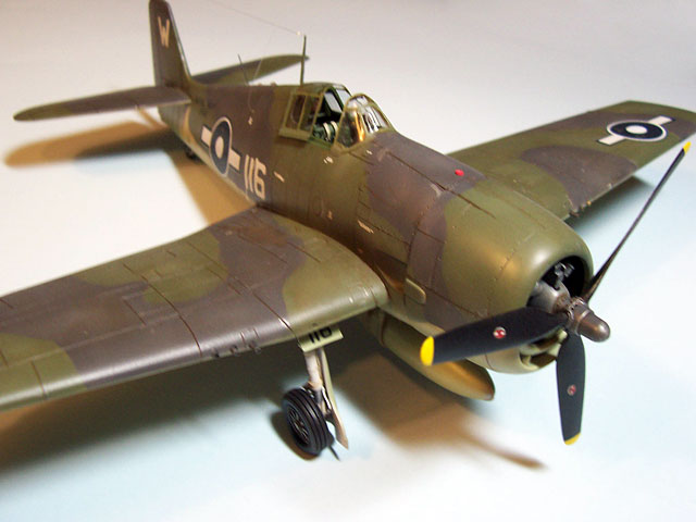
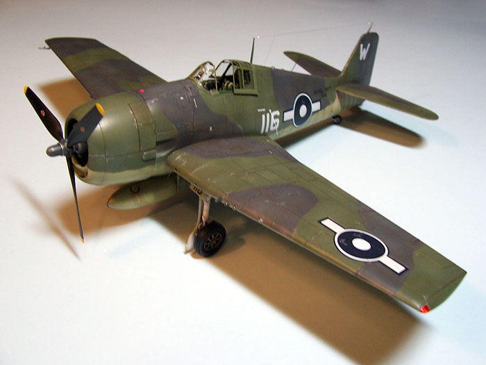
Hasegawa's 1/48 scale
Hellcat Mk.II
by
Michael Novosad
|
 |
|
Grumman Hellcat Mk.II |

HyperScale is proudly supported by
Squadron
While in attendance at the IPMS National Convention in Kansas City in
August of 2006, I was fortunate enough to win a set of White Dog decals
for Fleet Air Arm Corsairs and Hellcats. This prize was grabbed up in a
last minute scramble for prizes, so I really wasn’t sure what I had. I
was not familiar with this manufacturer at the time, but have since seen
reviews on models using these markings.
The set that I selected includes two sheets of decals for three
Corsairs (one Mark II and two Mark IV’s) and three Hellcats (One Mark I
and two Mark II’s). I decided to model a Mark II Hellcat in the markings
for an aircraft flown by S/Lt. R. Mackie, RCNVR, flying off the Royal
Navy Aircraft Carrier Indominable. During World II 1263 Hellcats, in
four marks were utilized by the FAA.
These aircraft were originally known at the “Gannet’, but the name
was changed back to Hellcat. The F6F-3 was known as the Mark II in
British colors.
Kit and Aftermarket Parts
The kit is Hasegawa's 1/48 scale F6F-3 Hellcat.
The aftermarket parts used in this build are as follows:
-
Cockpit Interior- True Details
TD48461
-
Wheels- True Details TD46012
-
Decals- White Dog 481001
-
Stencils- Aeromaster 148017
Cockpit Assembly and Painting
The cockpit is built from the True Details parts plus selected kit
parts. The resin parts were carefully removed from the casting stubs
with a razor saw. The two sides were labeled with a permanent marker to
avoid confusion during the final assembly. After careful dry-fitting and
alignment with the cockpit floor the side walls were super glued in
place to the fuselage sides.
I also elected to use the kit instrument panel as I felt this part was
more crisply formed than the resin parts. I first airbrushed the
instrument panel Tamiya Flat Black, and sealed it with Future for a
glossy finish. I then used 1/16” and 1/8” paper punches to punch out
individual dials as found on the Mike Grant Instrument Decal Sheet. Each
instrument face was transferred to the dial positions, then everything
was covered with Micro Sol decal solvent. Once dry each dial face was
given a small bead of Micro KrystalKleer. Various knobs and switches
were painted red, white or yellow.
Everything was then fixed in place on the left-hand side of the
fuselage, and everything fit just as advertised.
Engine Assembly
My first task was to drill a small hole in each cylinder head for the
future installation of ignition wires. The gear box is comprised of two
parts plus a nylon sleeve for the propeller shaft. These parts were
assembled and set aside to dry. The engine parts were fixed to a scrap
piece of foam board with masking tape, then airbrushed flat black.
I used 1/16” ID aluminum tubing to create the ten exhaust pipes. The kit
plastic exhausts lacked definition in my opinion, so the aluminum tubing
was used. After cutting and reaming the outlet ends of the individual
pipes I airbrushed them with Tamiya Flat Black, dry brushed with Testors
Rust, and a final light dry brushing with Silver Rub-n-Buff finished the
task. These parts would be installed once the model was completely
painted and just before the cowling was installed.
Fuselage Assembly
Once the cockpit interior was in place and properly aligned the two
fuselage halves were closed and sealed with Tenax. The fuselage back
immediately behind the cockpit took a bit of persuasion to close, but it
did. Some filler was required to finish the top and bottom seams. The
three navigation lights locations on the bottom of the aft fuselage were
drilled out and would be later filled with KrystalKleer and clear,
tinted colors. The cowling would be painted separately, but would be
held in place from the side with masking tape.
The two locations for the whip antennas were drilled out, and a small
stub of brass tube was used at the starboard side antenna entry
location. The whip antennae would be installed late in the construction.
Wing Assembly
The wings are comprised of three parts: the full span bottom and the
two wing tops. I carefully removed the wingtip navigation lights and the
landing light from the right wing by scribing and cutting with a sharp
Xacto blade. I also removed the gun port “backstops” as I planned to
replace the gun barrels with brass tubing. I glued strips of styrene
parallel to the gun ports, and about 1/4” back from the leading edges to
act as stops for the replacement gun barrels. After the wing tops and
bottoms were glued together I cleaned up the locations for the wing-tip
navigation lights. The clear sprue from the kit was used to create the
navigation lights. These were carefully sanded and buffed to size and
shape, and would be later coated with Tamiya Clear Red and Green.
One of the first tasks is to create painting masks for this model.
Using sheets of printer paper the outlines of the fuselage, wings and
stabilizers were made, then the limits of each color was sketched in the
appropriate locations. Each color was then labeled on the masks to avoid
confusion during the mask application and painting process.
The first color to be applied to the model is the Sky color. The
undersides were primed with flat white, and all panel lines were
preshaded with Tamiya XF-64 red brown. The preshading and Sky
applications were done in one session since the paints were all
compatible acrylics. This was allowed to dry for 24 hours, then a wash
of burnt umber, thinned with odorless thinner was applied over the
entire undersides with a wide, soft brush. This, too, was allowed to dry
for 24 hours. Last, a light seal coat of Future was applied to seal the
undersides. The model was set aside to again dry for 24 hours.
After the undersides were completely masked, the topsides were ready to
be painted. Using a plastic utility knife with snap-off blades tips each
color was separated from the main sheet. It is important to cut the
stencils on the outlines with a sharp blade to avoid ripping or fraying
the masks. Using rings of painters tape (sticky side out) each mask for
both colors were applied to the top surfaces of the model.
The Slate Green was the first color to be applied. First, the
appropriate masks were removed, and a base of the Tamiya XF-73 Dark
Green was applied to the exposed areas. Next, the XF-73 was tinted with
Tamiya Flat White and 91% isopropyl alcohol was applied to the surfaces,
but I avoided spraying too close to the masks. I wanted to achieve a
slightly darker outline. Last, the XF-73 was further mixed with Flat
White and more thinner. This mixture was then applied in a blotchy,
random manner over the first paint applications.
After the Dark Green had dried the XF-24 Dark Grey was applied. I
replaced the Dark Green masks, aligning them as carefully as possible
with the Dark Grey masking. The Dark Grey masks were then removed. The
Tamiya XF-24 was applied in a like manner at the Dark Green noted above.
Once the painting had thoroughly dried all masking was removed. A wash
of burnt umber, thinned with odorless thinner was applied over the
entire topsides with a wide, soft brush. This wash blends the various
over sprays and starts the panel line shading. This was allowed to dry
for 24 hours.
Paint chipping and scuff marks were replicated using a silver artist
pencil. The point was sharpened frequently to maintain the “scale” size
of the scuffs and scratches. This process normally works best on a flat
surface.
Two applications of Future were applied over the surfaces, and allowed
to dry for 24 hours. We have a warm air floor register in our den, so
the models are placed over the vent and allowed to dry. The warm furnace
air speeds up the drying process.
Finishing Tasks
The engine exhaust pipes were located and fixed in place with
superglue. The engine was set in place and the cowling was slipped over
the engine and glued in place. The eight brass tube gun barrels were
inserted and glued in place. The whip antennae were made from finely
stretched sprue and were glued in place with white glue. The antenna
wire was made from invisible thread with white painted blobs of white
glue used to represent insulators.
Decaling and Weathering
The decals were applied with MicroSet to place the individual
markings, and later MicroSol was applied to snuggle the decals in place.
Once the decals had dried a pin point wash of thinned burnt umber was
applied to all panel lines. I used thinned Tamiya flat black for exhaust
staining, and thinned Tamiya Deck Tan to create what I call wind
streaking (a very subtle application is in order) across the tops of the
wings. It was finished!
Model, Images and Text Copyright © 2007
by Michael Novosad
Page Created 08 July, 2007
Last Updated
24 December, 2007
Back to
HyperScale Main Page
|
 Home
| What's New |
Features |
Gallery |
Reviews |
Reference |
Forum |
Home
| What's New |
Features |
Gallery |
Reviews |
Reference |
Forum |