|
Legato 1/48
scale
Focke Wulf Fw
190 V1
by Floyd S.
Werner Jr.
|
 |
|
Focke
Wulf
Fw
190
V1 |

HyperScale is
proudly
supported by Squadron
Background
|
Legato
1/48
scale
Focke
Wulf
Fw
190
V1
Prod
code-LGMLK4822
Cost
$75.00
Reviewed
by
Floyd
S.
Werner,
Jr.
IPMS#
26266 |
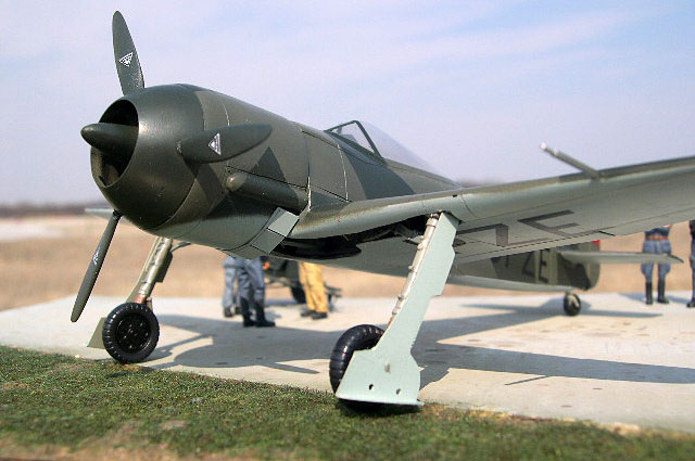
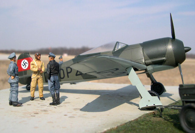
Wurger, Butcher
Bird, or
whatever you
call it the
FW-190 was one
of the great
warbirds of the
WWII. Before it
could become the
deadly bird of
prey the 190 had
to start
somewhere. That
started in June
1, 1939 in
Breman with the
first flight of
Kurt Tanks’s
greatest design.
A small compact
all metal
monoplane
fighter, the
FW-190 was
initially beset
with problems,
most notably by
the intense heat
from the engine.
The 190V-1
employed a
unique NACA type
cowling over the
spinner in an
attempt to
streamline the
bulbous radial
engine. This
cowling
arrangement was
found to not
work as
advertised. The
V-1 was re-engined
with the BMW801
engine and with
the
repositioning of
the cockpit aft
to counter the
heavier engine
the rest is
history.
The Kit
Legato’s
FW-190V-1 is
packaged in a
sturdy cardboard
box with an
instruction
sheet and
painting sheet.
The 29 pieces of
resin are light
grey and
relatively free
of defects. I
did have a
couple of
bubbles here and
there but
nothing that was
out of the
ordinary or in
an objectionable
place. You also
get a fret of
photo etch and
one transparent
canopy. The
decals are
printed by
Aviagraphics and
are very nicely
done.
I like to cut
all my parts
from the pour
stubs and clean
them up first. I
washed all the
parts in Dawn
grease cutting
dishwashing
liquid. The
whole separation
process took a
little longer
than I thought
it would, about
three hours.
Nothing out of
the ordinary but
it did seem
long.
Cockpit
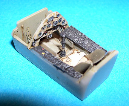 The
cockpit is the
normal starting
place and this
model is no
different. The
cockpit is a
mixture of resin
and photo etch. The
cockpit is the
normal starting
place and this
model is no
different. The
cockpit is a
mixture of resin
and photo etch.
Everything
fitted as
advertised.
I elected to
paint the entire
cockpit in RLM
02. There is
also the
possibility that
it could have
been RLM 66 but
I think that the
1939 date of
manufacture
leads to the RLM
02.
The wash was
burnt umber
artist oils with
a dry brush of
white and small
chips of silver
pencil. Just a
little as this
was a brand new
machine fresh
from the pre-war
factory.
Fuselage
Cutting the
fuselage halves
from their pour
stub is a time
consuming task.
Patience is
called for. This
task was more
like separating
a vacuform part.
I cut at an
angle and then
sanded the top
where the pour
plug were until
it was flat. I
added some
plastic channel
to the tail
wheel area to
mount the tail
wheel to. This
helped this
greatly. Once
that was done
the parts were
joined with
superglue from
the inside to
tack the pieces
together. Once I
was sure
everything was
aligned I added
superglue to the
seam on the
outside. One
thing I should
have done but
forgot was while
the halves were
separate I
should have
attached the
horizontal tail
with superglue
and then drilled
the mounting
holes from the
inside. This
would have made
attaching these
pieces easier
later.
Now that the
fuselage was
assembled how
far back do I
put the cockpit
tub as there are
no locating pin
and only vague
pictures in the
instructions. I
finally figured
out a way to do
it. I folded the
photo etch piece
for the deck
behind the pilot
and then placed
it in the
opening. I moved
it back until
the part could
move no more and
then inserted
the cockpit from
below to fit
this piece. It
actually worked
out pretty well
and everything
was aligned ,
including the
instrument
panel.
Click the
thumbnails below
to view larger
images:
[../../photogallery/photo00027964/real.htm]
Wings
Now came the
first really big
hurdle, the
wheel wells and
wings. The wings
are a typical
three piece
affair, one
lower and two
upper halves.
The issue is
where do you fit
the wheel wells.
Seems easy
enough but this
proved to be one
of the more
difficult tasks.
First off you
will have to
remove a lot of
resin from the
wheel well
opening to thin
the edges to a
more scale
appearance and
better fit the
wells
themselves.
There was dust
everywhere, but
I finally got a
good fit. Then
when I tried to
attach the top
wings they
needed the same
amount of
thinning to
allow the wheel
well to sit
properly and the
wings to attach
to the fuselage.
Go slow and test
fit often. Once
you have them in
place there is
the center piece
of the wheel
well that fits
someplace up
under the
cockpit and
should attach
the outer wheel
wells. It
doesn’t, not
really. First
off the
instructions are
vague at best as
to where it
goes. It
obviously does
not butt join
because then the
landing gear
mounts won’t
fit. I ended up
lining the rear
portion of the
wheel well which
allowed the
whole thing to
fit in the wing.
Then I added the
vertical portion
of the wheel
well. This was
offered up to
the wing to
check alignment
and it was fine.
The ailerons are
separate pieces.
My example had
some flaws in
them that needed
a little putty.
No big problem.
There were some
air bubbles on
my upper wing
half on the
trailing edge
that I filled
with superglue
and accelerator
before I
attached the
ailerons.
The Engine
The engine is a
key part of this
kit. I painted
my engine flat
black and dry
brushed silver
over the
cylinders. It
has some pieces
that have to be
aligned for the
prop to fit
properly as well
as the NACA
cowling. Dry
fit, dry fit,
dry fit. I got
lucky and mine
lined up. There
is no indication
on how far in or
out the cowling
it is suppose to
fit so align at
the back. The
engine mount
fits against the
vertical wheel
well piece. Then
the back of the
engine fits on
that. Now the
front portion of
the engine is
where the issue
comes into
effect. Should
it be glued to
the read portion
or inserted in
the cowling
someplace? If
you look at the
instructions you
should mount the
engine to the
front of the
cowling. This
doesn’t work as
it will
interfere with
the NACA
cowling. I
finally ended up
just gluing it
to the back
piece and
drilling a hole
for the
propeller shaft.
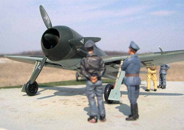
The NACA cowling
on my example
was round but
the opening
where the prop
comes through
was not. It was
relatively
simple to sand
it so that it
was round. I
wrapped
sandpaper around
a round brush
handle and went
to town. Inside
this piece goes
the inner prop
hub. I just
glued the prop
hub to the NACA
cowling ensuring
that it was
aligned with the
holes for the
props. Then the
NACA assembly
was attached to
the normal
cowling and the
fit was actually
pretty nice. I
had to open the
holes for the
propeller
blades.
Bringing the
wings together
revealed some
issues that
would have to be
addressed. I
noticed that the
dihedral was too
shallow and that
the left wing at
the root was not
completely
molded. It was
about an 1/8th
inch too short
at the back but
fit fine at the
front. What to
do? First off I
decided to deal
with the
dihedral by
using my wife’s
heat gun for
stamping. I kept
it moving and
when I could
tell that the
resin was
pliable I added
gentle pressure
to get some
dihedral. Just
hold it until
the wings cool.
This technique
is not for the
faint of heart.
For the wing
root I mixed two
part epoxy putty
and filled the
area. That was
actually pretty
easy.
Next problem
area was the
horizontal
tails. The tails
were canted aft
and that would
not do. At first
I thought what
the heck I’ll
just substitute
a set of Tamiya
ones, but
unfortunately
the Tamiya ones
are too large.
So now I had to
figure out how
to make do with
what was given
to me. First
off, I drilled
mounting holes
to see how much
I was talking
about. The gap
was pretty
substantial if
the tail was
going to be
straight. Using
hypodermic
needles as
mounts I leveled
everything out.
The resulting
gap was then
filled with
epoxy putty.
This actually
worked rather
well. I was
pleasantly
surprised at how
easy it was.
With the wings,
fuselage, and
tail all
together it was
time to wash the
model and prime
it. I used
ALCLAD grey
primer to check
for flaws and
there were many.
A little Tamiya
putty here and
there and
another coat of
primer and it
was time for
paint.
Canopy
There is only
one canopy and
it is different
than other
canopies from
any injection
kit so you only
get one shot to
cut it open. I
chickened out,
but with a
reason. The
FW-190V-1 had
the cockpit
situated forward
and if you cut
and reposition
the canopy open
you won’t notice
it as much. I
needed to cut
the canopy from
the backing and
this was very
easy. I used my
olfa cutter to
cut the long
portion and
scissors on the
front portion.
The whole
process was
pretty easy. The
canopy was
masked with
Tamiya tape and
painted RLM 02
as a base color
prior to the
camouflage being
painted.
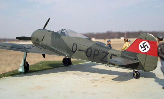
Painting
You are given
two choices for
the 190V-1. The
way it looked
when it rolled
out of the
factory in RLM
63 Light Grey
overall or the
way it was test
flown in RLM
65/70/71. I
elected the
tactical look
for my V-1. My
Bf-109V-1 is
overall RLM 63
so I wanted
something
different for
this model.
As this was a
factory fresh
machine it would
have no dirt and
grime so I
elected not to
preshade the
model. I first
sprayed the
Gunze RLM 65 on
the bottom.
Masked it off
with Tamiya tape
and then sprayed
the red band on
the tail and
masked it off
too. The Gunze
RLM 70 Dark
Green was
sprayed
completely over
the topside.
Once it was
dried, utilizing
the kit
instructions and
looking at the
pictures in my
references I
masked off the
dark green. The
Gunze RLM 71 was
sprayed over the
masking. Once
the masking tape
was removed
there was some
touchup that
needed to be
done but overall
I was pretty
happy with the
look.
Some more
construction...
Now that the
colors were on I
like to attach
as many parts as
possible. This
starts with the
landing gear. I
drilled holes
for them to fit
into. This whole
process worked
out rather well.
I used 5 minute
epoxy to add
additional
strength and
allow me to get
the angles
correct. While I
was at it I
added the tail
wheel as well.
It should all be
easy now,
right?. Just add
the photo etch
gear doors and
gloss, but when
I tried to add
the doors there
was something
amiss. The doors
were freakin
huge. Even if I
cut them down
they would not
fit, not even
close. What to
do now? These
doors are unique
to the V-1. I
took the photo
etch to my
scanner and
reduced it in
size by 15% and
print it out on
some paper. I
then used double
sided tape to
attach the paper
to a piece of
.005 plastic.
Then I carefully
cut them out. I
added the same
rivet detail
with my Rosie
the Riveter that
was on the photo
etch part. It
looks just like
the photo etch
part, I was
happy and proud
of the look. I
did have to make
a compromise
though. There
are two holes on
the door but I
had to drill an
additional hole
to aid in
mounting the
door to the
strut that
wasn’t on the
real thing. Oh
well I can live
with it.
Once the gear
was attached, it
was time to add
the gloss coat.
I used ALCLAD
Clear Gloss over
the entire
model, including
the canopy. It
was time for the
decals.
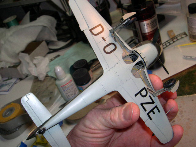
Decals
The decals are
made by
Aviagraphics. As
such they are
quite thin and
completely
opaque. The
swastika for the
tail is a one
piece affair
with a white
background. Once
placed over the
red tail band it
was perfect. The
rest of the
markings are
black codes. The
ones for the
wings are
separate
letters. The
fuselage ones
are a one piece
affair. They are
fragile so be
careful. They
responded well
with Solvaset.
The clear
carrier
disappeared
completely. I
normally
overcoat the
decals with
another coat of
clear but these
were so thin
that I didn’t
feel there was a
need so I
oversprayed
everything with
Model Master
Acrylic
Semi-Gloss.
Remember it was
a factory fresh
machine and was
made to look
beautiful for
the brass. Gloss
was too glossy
but semi-gloss
was just right.
I had to make an
instrument panel
cover. I
couldn’t see the
aircraft as not
having one. I
used one from
another resin
kit as a
template and cut
one out of
brass. I primed
it and painted
it RLM 66. Now
to just add the
canopy.
Adding the
canopy was not
as easy as it
sounded. Because
it was a
vacuform canopy
there was very
little surface
to attach it. I
used some .020
rod and ran it
around the aft
portion of the
canopy. This
gave some
additional area
to use. I used a
combination of
white glue and
watch crystal
cement to get a
good join. I
used white glue
to fair
everything in. I
touched up the
white glue with
the appropriate
paint.
Heck it should
be all over but
the photos now
right? Wrong!
The final thing
to add was the
prop blades.
These have no
mounting points
to go into the
holes in the
NACA cowling. I
drilled a hole
and inserted
.025 rod into
each blade. Once
I had that done
the holes were
too big in the
cowling. I mixed
up some two part
epoxy putty and
carefully put it
in the holes. I
pushed the
blades into the
putty and to set
everything with
just a drop of
superglue to
hold it while
the putty cured.
This actually
provided a
strong bond. I
was surprised
and pleased.
The final part
was the photo
etch cowl flaps
on the lower
cowling. With
that the model
was done. I
elected not to
weather or put a
wash on it
because I liked
the way it
looked.
If you want a
FW-190V-1 this
is the only one
in town and the
only one likely
to be made, but
it is not an
easy build. It
takes a lot of
skill, a bit of
luck, and it
definitely
stretched my
abilities. I can
recommend it to
experienced
resin model
builders only.
Did I have fun?
Yes, almost
every minute.
I’m glad it is
done and it adds
a unique looking
airplane to my
collection.
Thanks to David
Cooper from
Cooper Models
for the review
copy. You can
get yours and
check out some
other great kits
at
http://www.coopersmodels.com/Home.html
or by emailing
him at
Proteus440@msn.com
. Let him know
you heard about
it here.
Focke-Wulf
Fw-190A: An
illustrated
history of the
Luftwaffe’s
Legendary
Fighter
Aircraft,
Dietmar Hermann,
Ulrich Leverenz,
and Eberhard
Weber, Schiffer
Publicastions,
2004, ISBN
0-7643-1940-X
(the best source
for V-1
information and
photos)
Focke Wulf
Jagdflugzueg,
Peter Rodeike,
ISBN 3-923
457-44-8
Click the
thumbnails below
to view larger
images:
[../../photogallery/photo00024806/real.htm]
Model, Images &
Text Copyright
©
2007 by Floyd S.
Werner Jr.
Page Created 01
May, 2007
Last Updated
24 December, 2007
Back to
HyperScale Main Page |
 Home
| What's New |
Features |
Gallery |
Reviews |
Reference |
Forum |
Home
| What's New |
Features |
Gallery |
Reviews |
Reference |
Forum |